Custom machining fixtures, made to your drawings
We machine fixture plates, locating blocks and sample holders to your drawings for equipment assembly, workholding and inspection setups.
In-house CNC machining and dimensional inspection.
Send a drawing, CAD file or useful part description with the intended use. Complete fixture design and calibration require separate agreement.
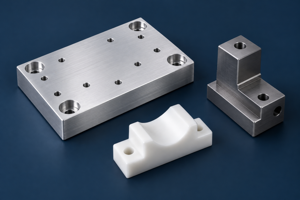
Plates, blocks and holders for your setup
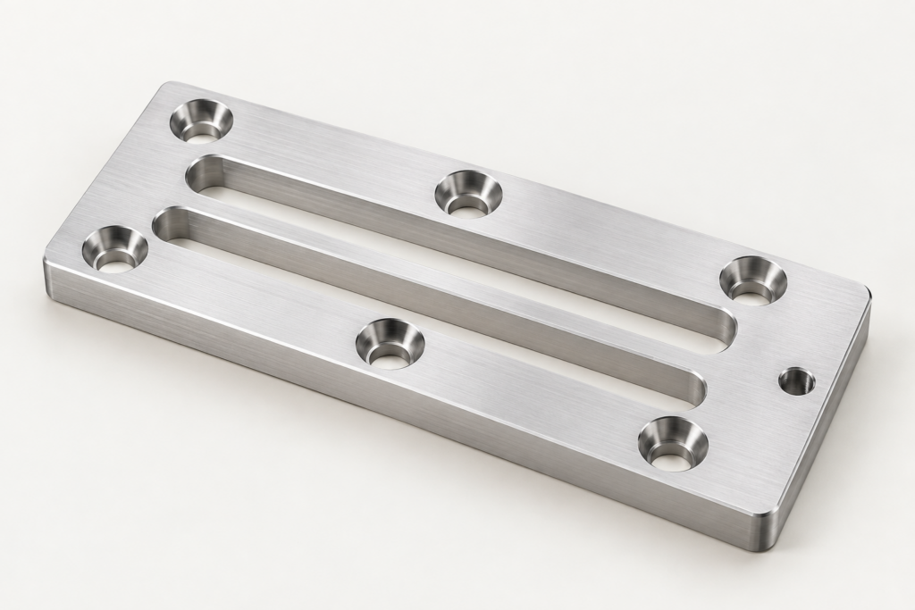
Fixture plates and tooling plates
A machined base brings mounting points and locating features onto a shared reference. Custom geometry fits the machine, assembly or component interface that a standard plate cannot accommodate.
Identify the datum origin, locating holes and mounting pattern. Include underside clearance and the faces that contact the supporting structure.
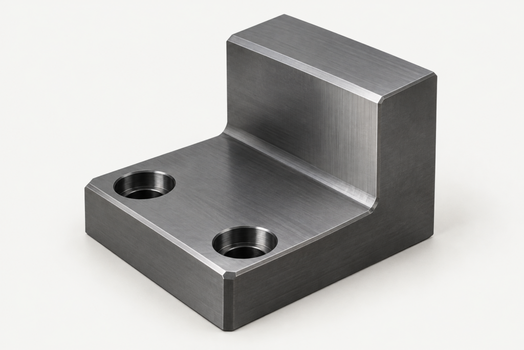
Locating blocks and stops
Stepped blocks, shoulders and stops establish contact points. Separate replaceable components let you change a worn contact element without replacing the larger base.
Show the contact faces and mating interfaces, with the required material condition. Specify any hardness or treatment needed on a wear surface.
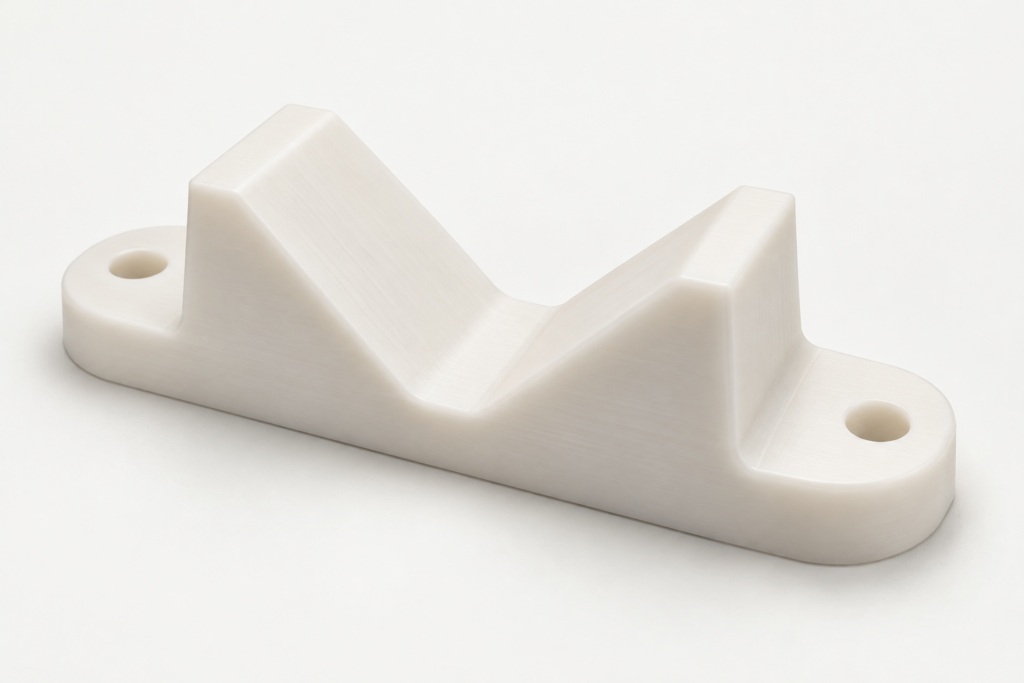
Sample holders and support nests
A shaped support holds a part in a defined orientation for assembly or inspection. The contact geometry and access around it matter as much as the outside dimensions.
Show the permitted contact areas and the clearance needed for measuring tools and loading.
AI-generated illustrations show example component forms, not delivered projects or measured fixture performance.
Define the features that locate the part
Locators establish position; clamps hold the workpiece against them. Show which features locate, support or fasten the part: individual component dimensions alone do not define the alignment of an assembled setup.
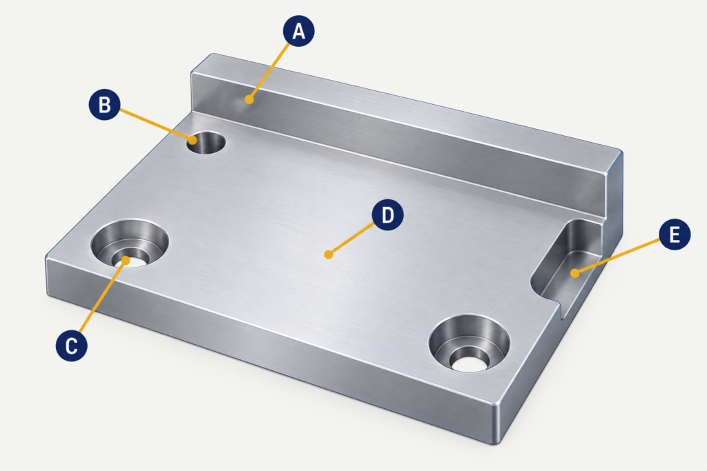
Illustrative features: A — reference face; B — locating bore; C — mounting hole; D — support plane; E — relief and access.
Datum faces and contact surfaces
Name the reference faces and distinguish the surfaces that contact the workpiece or base from relieved clearance surfaces.
Locating holes and mounting holes
Specify the locating-hole fit and its position relative to the datum faces separately. Include the mating pin or component information when it affects the fit. For fasteners, identify the thread standard, depth, counterbore and any through clearance rather than treating every hole as a locating feature.
Support plane and access
For a flatness requirement, identify the controlled area, support condition and measurement state. Also show the space needed for loading, cutting tools or measuring probes, and any chip-clearance or relief features. A flatness callout on one defined contact area does not describe the whole installed fixture.
Material and finish follow the working interface
A base plate, replaceable stop and sample-contact insert can use different materials. Define each grade, condition and functional surface around its role in the assembly.
Steel locating and wear components
1018, 1045 and 4140 are distinct grade options for drawing-based assessment. Specify the required condition and hardness where applicable, together with any heat treatment or corrosion protection. Do not leave a functional contact face defined only as “steel”.
POM sample-contact components
For POM locating parts, identify POM-C or POM-H and the required measurement state. Include the sample-contact geometry and how the component is supported in use so that the material and dimensional requirements can be assessed together.
Mark whether locating holes and contact faces are accepted before or after finishing, and identify any masking. Specialist finishing is arranged through selected partners to the project specification.
Inspection against the component drawing
Identify the drawing revision and the dimensions that control assembly or location. We agree the inspection method and required records for those features before manufacture. CMM measurement, pin gauges and thread gauges are available where suited to the specified features and access.
Dimensional reports and first-article records can be included as agreed in your order. Identify the features requiring recorded results; full-dimensional inspection of every component is quoted separately.
Dimensional inspection checks the supplied parts against the agreed drawing. Fixture-system calibration or repeatability testing is a separate scope. If your inspection fixtures need functional acceptance with a sample or installed system, define the method, conditions and acceptance criteria for separate agreement.
Match the parts to the assembly
Equipment assembly tooling
A tooling plate with locating blocks can position components during assembly. Send the assembly drawing and component identities when the relationship between mating interfaces governs the job.
Inspection and sample holding
A holder can present a sample to a probe, gauge or operator while keeping the required surfaces accessible. Include the sample geometry and measurement access envelope so the holder can be machined to suit that setup.
Replacement and repeat parts
For repeat parts, confirm the drawing revision, mating interfaces, material, finish and inspection requirements. Identify changes to interfaces or contact surfaces before a replacement is made.