CNC Machining Tolerances
CNC machining tolerances define the permitted variation of a dimension or geometric characteristic. Start with the function: a bore’s diameter, its position relative to drawing datums and a mounting face’s flatness are different requirements.
There is no single standard CNC machining tolerance for every feature. Individual callouts, general specifications and the governing drawing standard define what is required. The manufacturing and inspection methods must then suit the actual part.
Read the Allowed Interval
A tolerance tells you which values are acceptable, rather than how close a particular measured part happens to be to nominal. These worked examples use millimetres and illustrate notation; they are not measured production results.
Bilateral: 10.00 ±0.05 mm
The nominal size is 10.00 mm. The lower limit is 9.95 mm and the upper limit is 10.05 mm. Subtracting nominal from each limit gives the lower deviation of −0.05 mm and upper deviation of +0.05 mm. The total tolerance width is 0.10 mm: twice the 0.05 mm allowance on either side of nominal. Writing the same interval as explicit limits, 9.95–10.05 mm, makes the endpoints visible.
Unilateral: 10.00 +0.10/−0.00 mm
The lower limit is 10.00 mm and the upper limit is 10.10 mm. This interval also has a total width of 0.10 mm, but permits different sizes from the bilateral example. Moving the allowance to one side of an unchanged nominal changes the acceptable interval.
An interval can also be asymmetric on both sides of nominal. Read the actual upper and lower deviations; do not assume that every two-sided callout is centred or that its total width equals either deviation alone.
Choose the Feature Relationship
A hole can meet its diameter limits and still be in the wrong place for the mating component. Size, location and form answer different assembly questions. The applicable ISO or ASME drawing rules and explicit callouts determine the full requirement.
Size: Does the Mating Feature Fit?
Diameter limits control the specified size of a hole or shaft. Thickness and width are also size requirements. Identify the actual feature, its limits and any measurement definition required by the drawing. A diameter limit does not locate the hole axis relative to the surrounding mounting faces.
Position: Where Is the Feature?
A position requirement relates the controlled feature to its specified theoretically exact location and datum system, as applicable. Choose functional references that represent how the part mounts or locates. A tight hole diameter cannot compensate for a misplaced hole pattern, and tighter coordinate dimensions are not automatically equivalent to a geometric position callout.
Flatness: What Form Must the Face Have?
A flatness requirement constrains the surface within a zone between two parallel planes; the flatness zone itself has no datum reference. Parallelism and perpendicularity control orientation relative to a specified datum. Do not substitute a thickness limit for required flatness, or flatness for the orientation between two mounting faces.
Profile can control a line or surface relative to its specified geometry, with datum references where required. Runout addresses variation during rotation about a specified datum axis. These controls need the actual drawing definition; neither is interchangeable with a simple diameter tolerance.
ISO 1101:2017 defines the language and interpretation of geometric specifications. It establishes drawing rules, rather than a supplier’s ability to manufacture every stated requirement.
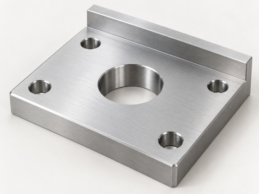
Illustrative locating-part geometry supports the feature discussion; it is not a controlled customer drawing or a photographed delivery.
General Tolerances and Individual Callouts
A drawing-wide note can define requirements for features without individual tolerance indications. The reference needs an identifiable standard, edition and applicable class or specification. An ISO 2768 class is not one fixed ± value for every nominal size.
Use individual callouts for the interfaces whose function needs a specific size, location, form or orientation. Clarify contradictory notes or differences between the 2D drawing and 3D model before manufacture, with the controlling revision identified.
Check the Current Reference
At our 31 October 2026 catalogue check, ISO 2768-1:1989, covering general linear and angular tolerances, remained published. The replacement ISO 2768 edition 2 project was under publication, rather than already published. Recheck the current record when issuing a new drawing.
The catalogue lists ISO 2768-2:1989 as withdrawn and revised by ISO 22081:2021. This does not make ISO 22081 an automatic replacement for every part of ISO 2768 or a direct swap of its old numeric classes. Agree how a legacy drawing is to be interpreted before changing its reference.
These notes describe public catalogue status and scope. Apply the specified standard’s actual requirements to the drawing; the full standards and their tolerance tables are not reproduced here.
Check Both Parts in a Mating Pair
A nominal hole-and-shaft size is not enough to calculate the possible clearance. Both permitted intervals matter. In this illustrative example, the hole diameter is 20.00–20.04 mm and the shaft diameter is 19.96–19.98 mm.
Minimum Diametral Clearance
Smallest hole minus largest shaft: 20.00 − 19.98 = 0.02 mm.
Maximum Diametral Clearance
Largest hole minus smallest shaft: 20.04 − 19.96 = 0.08 mm.
This is a worst-case size calculation for ideal aligned circular features in the same measurement state, not an ISO fit designation or an assembly guarantee. Form, alignment, finish, coatings and operating temperature need their own consideration. A multi-part assembly can also accumulate variation across several interfaces.
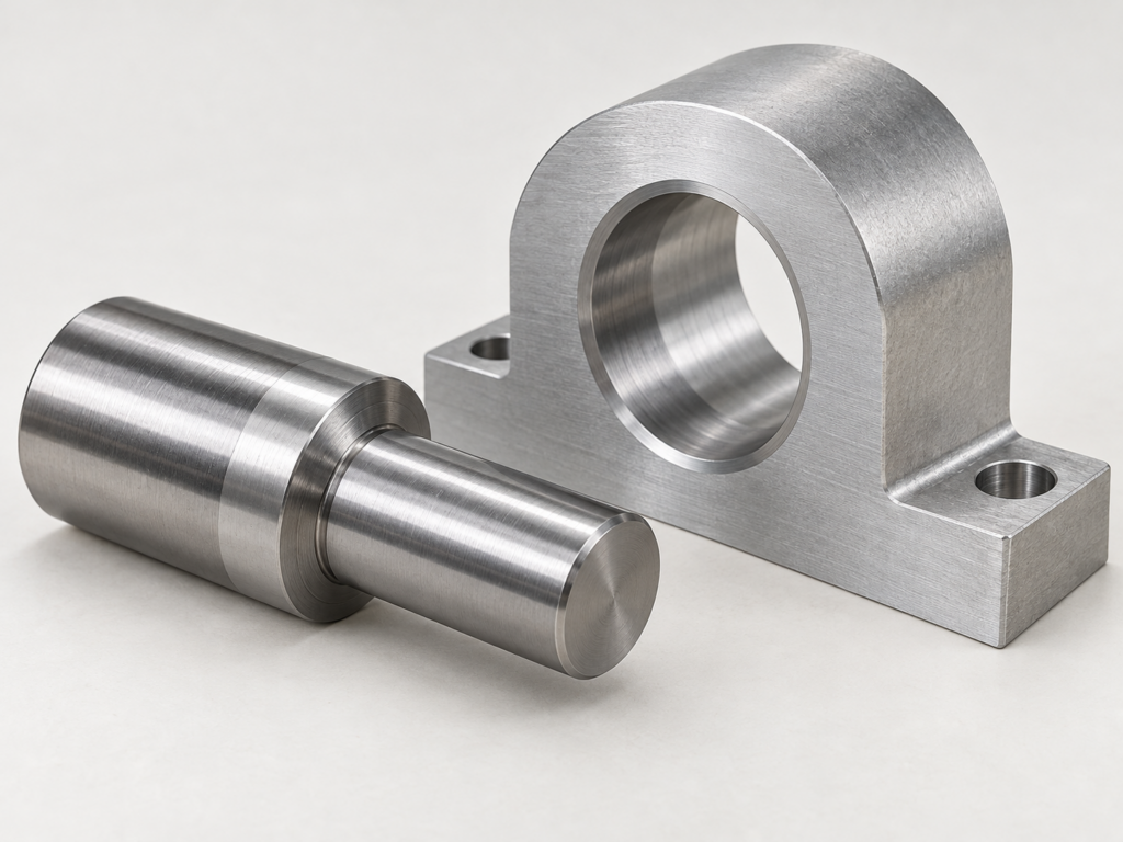
AI illustration of a shaft and mating bore; the worked limits above are authored examples, not dimensions measured from the image.
Put Tight Requirements Where They Matter
Tighter tolerances can add work when the existing route and measurement method no longer provide sufficient control. The useful question is which feature needs the smaller variation and what must change to achieve it.
Geometry and Setup
Reclamping a part transfers its location to another setup, introducing another source of location and orientation error between features. Thin or poorly supported sections can deflect under cutting or clamping forces; a face machined flat under clamp load can change form when released. Identify which features must relate to each other and whether they can be finished from one setup. Tool access and internal radii also affect the available route. Discuss those relationships before tightening every dimension.
Material and Processing State
Removing material can redistribute residual stress and allow a part to distort. Temperature changes can alter both a feature’s size and the clearance between mating materials, so inspection at one temperature does not establish the fit at every operating temperature. Define the material condition and acceptance state, including whether critical dimensions apply after heat treatment or a specialist finish. Coating thickness is not a universal conversion to the dimensional change of every hole, thread or outside feature.
Inspection and Records
Smaller allowable variation can require a different measuring method, setup, sampling strategy or specialist verification. Full-dimensional or per-part reporting adds a separate documentation scope. There is no useful universal percentage premium: cost depends on the actual geometry, material, quantity and acceptance work.
Match Inspection to the Requirement
Select a method for the quantity being checked. Measurement range, access, support, temperature, point selection and task-specific uncertainty matter alongside the instrument’s specification. A fine display resolution alone does not establish reliable acceptance of a tight tolerance.
Diameter and Other Size Features
A suitable micrometer, bore gauge or optical method may measure the required size, depending on the feature and access. Limit gauges can check an agreed acceptance condition without providing a complete dimensional map. Define what result and record the order needs, rather than choosing a tool solely from its displayed decimal places.
Position and Datum Relationships
CMM or suitable optical measurement can evaluate coordinate and geometric relationships within the method’s applicable scope. The datum setup, probe access, number and distribution of points, evaluation and workpiece condition affect the result. A CMM’s presence is not evidence that every feature can be accepted at the same tolerance.
Flatness and Surface Requirements
Flatness assessment needs appropriate support and a method covering the specified surface, such as a suitably levelled indicator scan or a suitable CMM strategy. A few thickness measurements do not by themselves describe its form. Surface roughness is another quantity, with its own parameter, unit, direction and measurement conditions. A lower Ra value does not automatically establish tighter size or flatness.
Mitutoyo’s Quick Guide to Measurement explains how the task, probe, environment, workpiece and evaluation contribute to CMM measurement uncertainty. Agree the inspection approach and the applicable conformance decision rule before relying on a result near a specification limit.
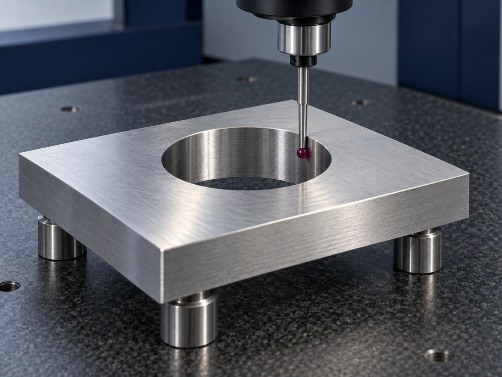
AI illustration of dimensional inspection; no actual measurement reading, factory equipment photograph or inspection report is represented.
What Great Machining Can Assess for Your Part
For selected stable, accessible metal dimensions in the 3–100 mm range, our typical reference is ±0.05 mm, with drawing requirements taking priority. Suitable precision metal features, generally no larger than 100 mm, can be assessed down to ±0.01 mm after reviewing material, geometry, datums, machining and inspection. Tighter ground or specially finished features are considered separately.
A selected 100 × 100 mm functional face can be assessed for 0.03 mm flatness with its full area, support and measurement state defined. This is a feature-specific scope, not a tolerance for all dimensions or a value to extrapolate to larger faces.
Explore our CNC machining services for the manufacturing route, or Aluminium CNC machining for grade, material form and finishing considerations. Inspection methods and documents explains the company’s verification and reporting options.
Release a Drawing That Can Be Quoted
Identify the functional features and datum scheme, state the applicable general references and resolve the drawing revision. Include the material condition, final finish and acceptance state, quantity and any required dimensional or first-article records. Those details let the quotation address both manufacture and verification.
If the design is still developing, a useful description, model or drawing can start a discussion. For confidential designs, enquire without attachments first so we can arrange an NDA and file-transfer method. The current quote form is for non-confidential files.