CNC Turning Services
Custom metal and plastic shafts, sleeves, spacers and threaded parts, made to your drawing for the next assembly. Great Machining combines in-house turning and mill-turn machining with agreed finishing and inspection, from your first prototype to repeat batches.
10 CNC lathes · 4 mill-turn machines
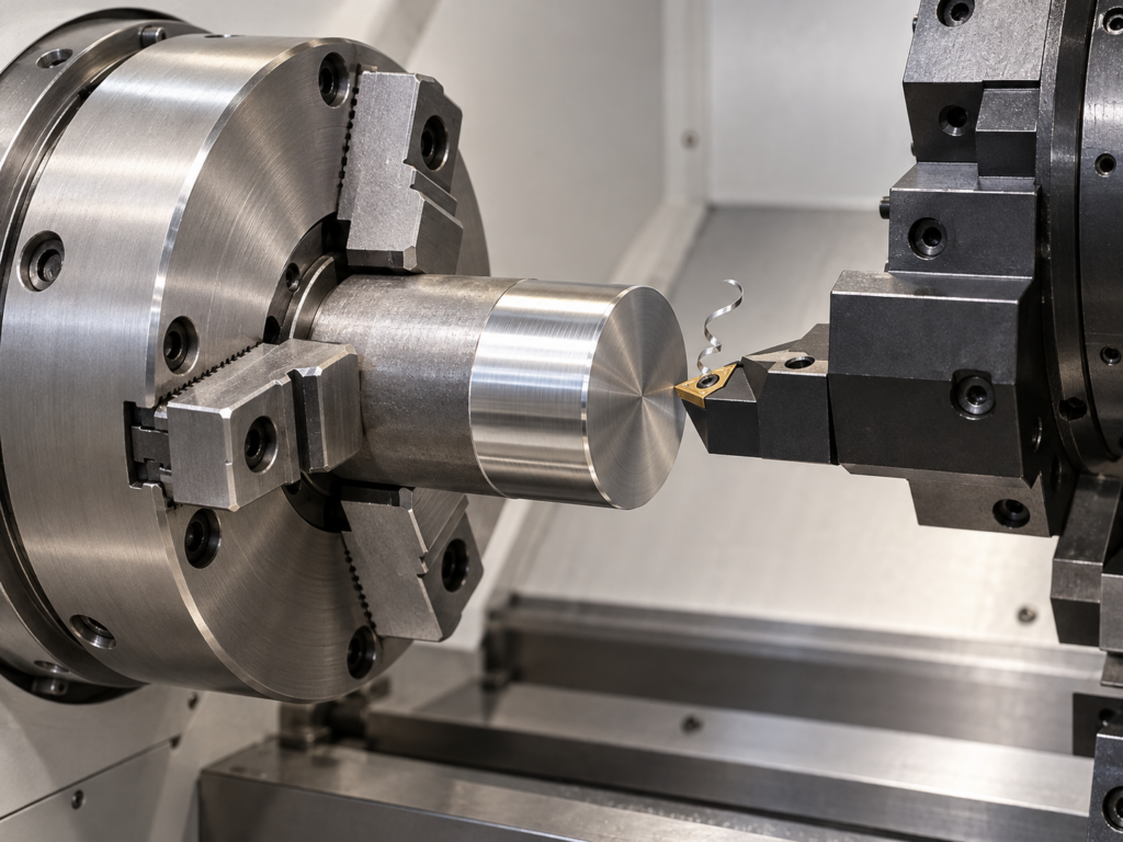
CNC turning process — illustration.
Turned Parts for Your Next Assembly
We machine rotational parts with the locating, mating and fastening features your assembly needs, from a simple pin to a bored, threaded fitting.
Representative geometry illustrations.
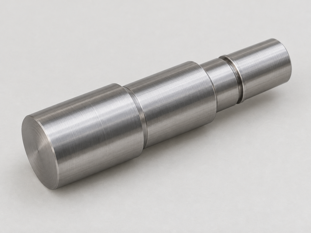
Short and Stepped Shafts / Pins
Locating diameters, shoulders, retaining grooves and end features for alignment and mounting. Short shafts and locating pins share the same need for clear mating dimensions and reference surfaces.
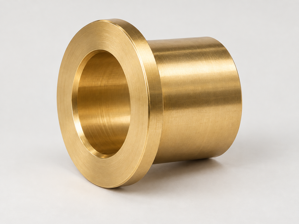
Bushings and Sleeves
Through-bores, stepped outside diameters and flanged ends for guiding, spacing or locating another component. The bore, outside diameter and length work together to establish the required fit.
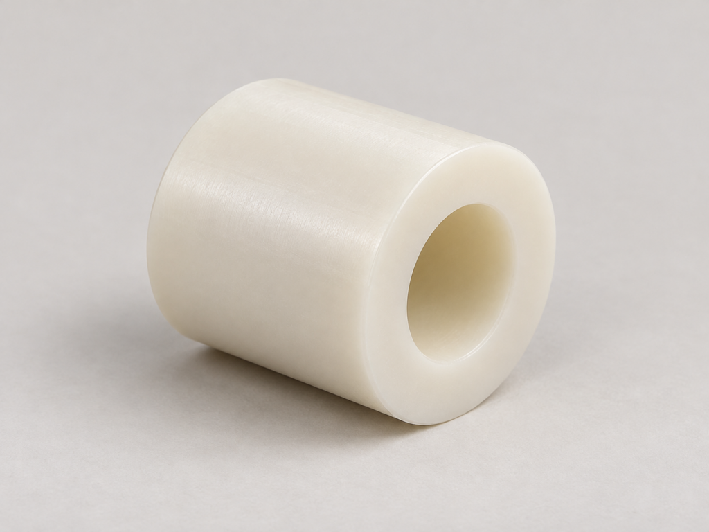
Spacers, Collars and Flanged Parts
Axial spacers, locating collars, flanges and bored hubs for positioning components. Roller and pulley profiles can combine concentric diameters and grooves with drawing-defined faces and secondary features.
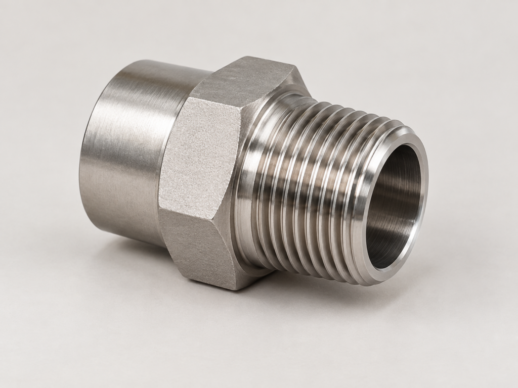
Threaded Parts and Fittings
Fittings, connectors and valve or pump component geometries with internal or external threads, axial passages and accessible side features. Knobs, dials and small cylindrical housings add adjustment or enclosure interfaces. Pressure, sealing and complete enclosure requirements are specified for the application.
In-House Turning and Mill-Turn Capabilities
Our turning team machines the cylindrical body and its mating features in-house, then adds accessible side features through mill-turn or secondary milling.
10 CNC Lathes
Outside and inside diameters, axial drilling and boring, facing, shoulders, grooves, and internal or external threads.
4 Mill-Turn Machines
Rotational parts with side holes, slots, flats or keyways, where tool access and the selected setup permit the feature combination.
| Capability | Working range | What determines feasibility |
|---|---|---|
| Outside diameter | Approximately Ø3–250 mm | Material, stock, gripping length and tool access |
| Part length | Up to 600 mm | Diameter, rigidity, workholding and support for slender sections |
| Combined turned and milled features | Drawing-based | Machine access, clamping and the relationship between features |
Diameter and length limits are assessed independently. The smallest diameter cannot be combined with the greatest length as one stated capability.
For components needing several processes, explore our CNC machining services.
316L Sleeves with Controlled ID and OD Fits
For this 100-piece 316L sleeve order, we machined two mating diameters and a fine functional surface before passivation and final inspection.
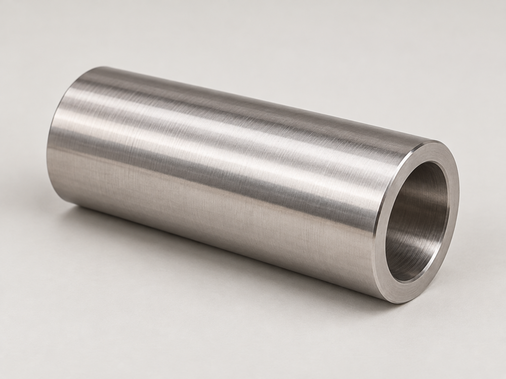
| Project detail | Requirement |
|---|---|
| Material and quantity | 316L stainless steel · 100 pieces |
| Nominal geometry | Ø18 mm outside · Ø10 mm bore · 45 mm long |
| Outside diameter | 18.000 ±0.010 mm |
| Inside diameter | 10.000–10.020 mm |
| Selected fit surface | Ra ≤0.8 µm |
Turning and finish fitting established the mating surfaces. Controlled deburring addressed the edges before passivation; the agreed diameters, length and surface requirements remained separate inspection items.
Machining and process inspection took 12 working days, followed by 3 working days for passivation and final inspection: 15 working days in total for this project. Your quotation sets the schedule for your own material, geometry and finish.
316L sleeve project — illustration.
More Turned-Part Geometries
Representative geometry illustrations; each shows a different material and feature combination.
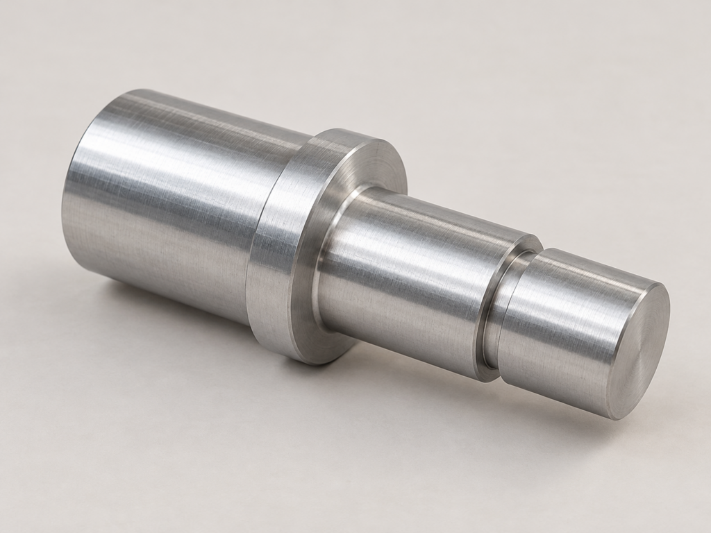
Aluminum stepped shaft: A locating shoulder and retaining groove define the shaft’s axial position.
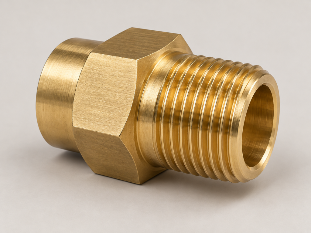
C36000 brass fitting: An axial passage and external thread combine with wrench flats for assembly.
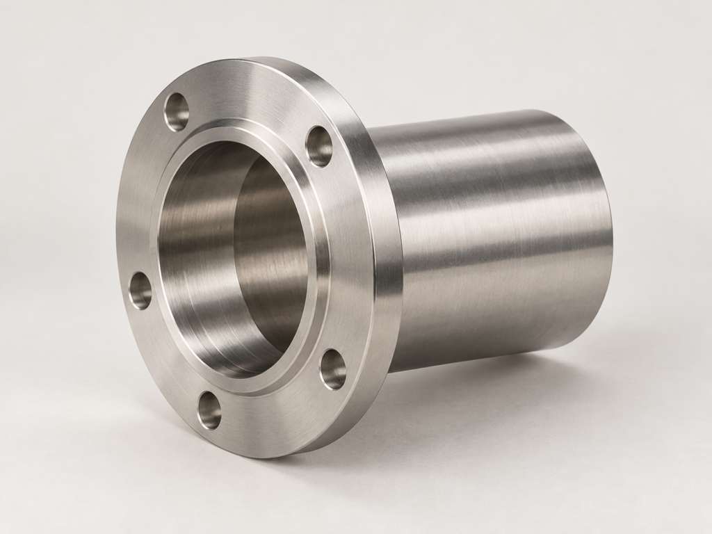
Stainless steel flanged sleeve: A bore and flange face create distinct radial and axial mating interfaces.
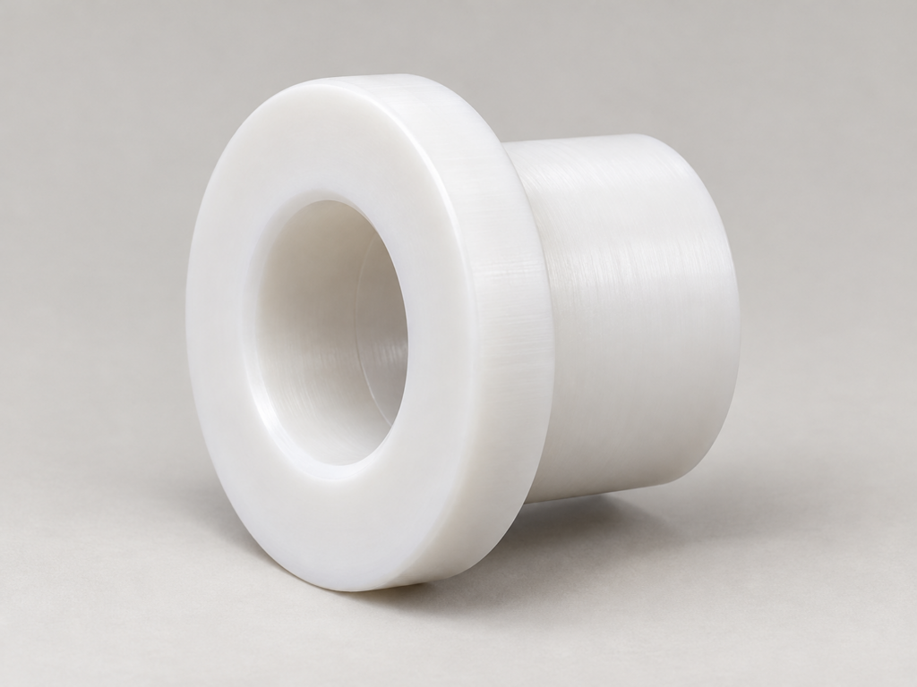
POM spacer: A thick wall and broad locating face provide a supported plastic geometry for fit evaluation.
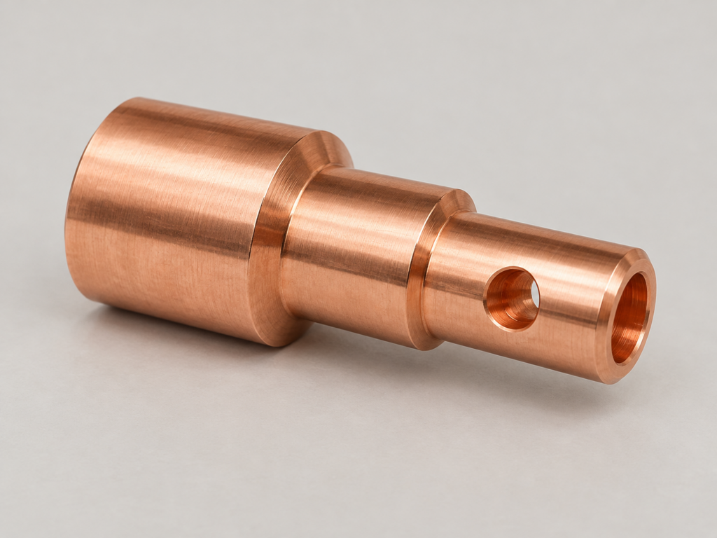
C11000 copper contact: Stepped contact surfaces and a cross-hole bring burr control into the connection detail.
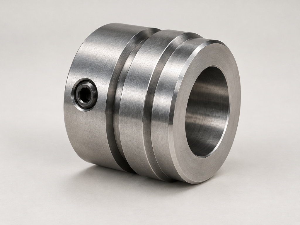
Steel grooved collar: A concentric bore and groove combine with a side feature for locating or retention.
Metal and Plastic Materials for CNC Turning
We source machining stock for your specified grade, material state and part geometry, including required brands, standards and material documents.
Lightweight sleeves, collars and stepped profiles.
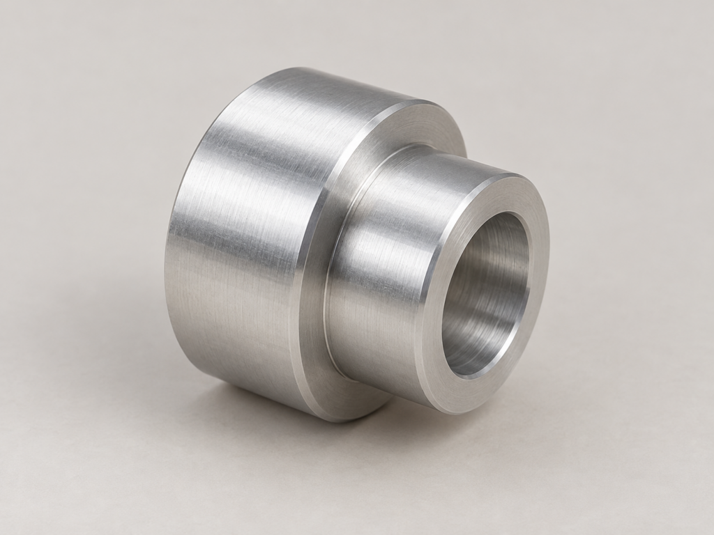
6061 and 6082 require their own specified standard and temper. Anodized appearance, masking and final fit are agreed for the selected alloy. See aluminum machining for grade and finishing detail.
Threaded fittings, inserts and small connectors.
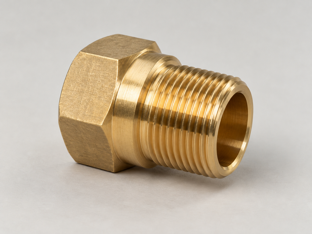
The actual alloy, intended medium or application, and material documents determine suitability. Lead-free status requires alloy-specific evidence.
Turned contacts and connector details.
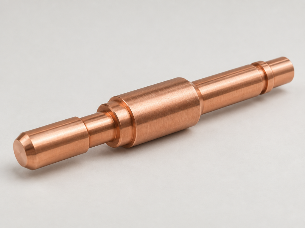
Material state, contact surfaces, burr limits and any plating define the order. Material conductivity alone does not establish finished-assembly performance.
Shafts, locating pins and mechanical sleeves.
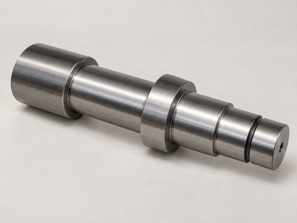
The grades are not interchangeable. Hardness, heat treatment and surface protection determine the final machining and inspection sequence.
Sleeves, fittings and instrument components.
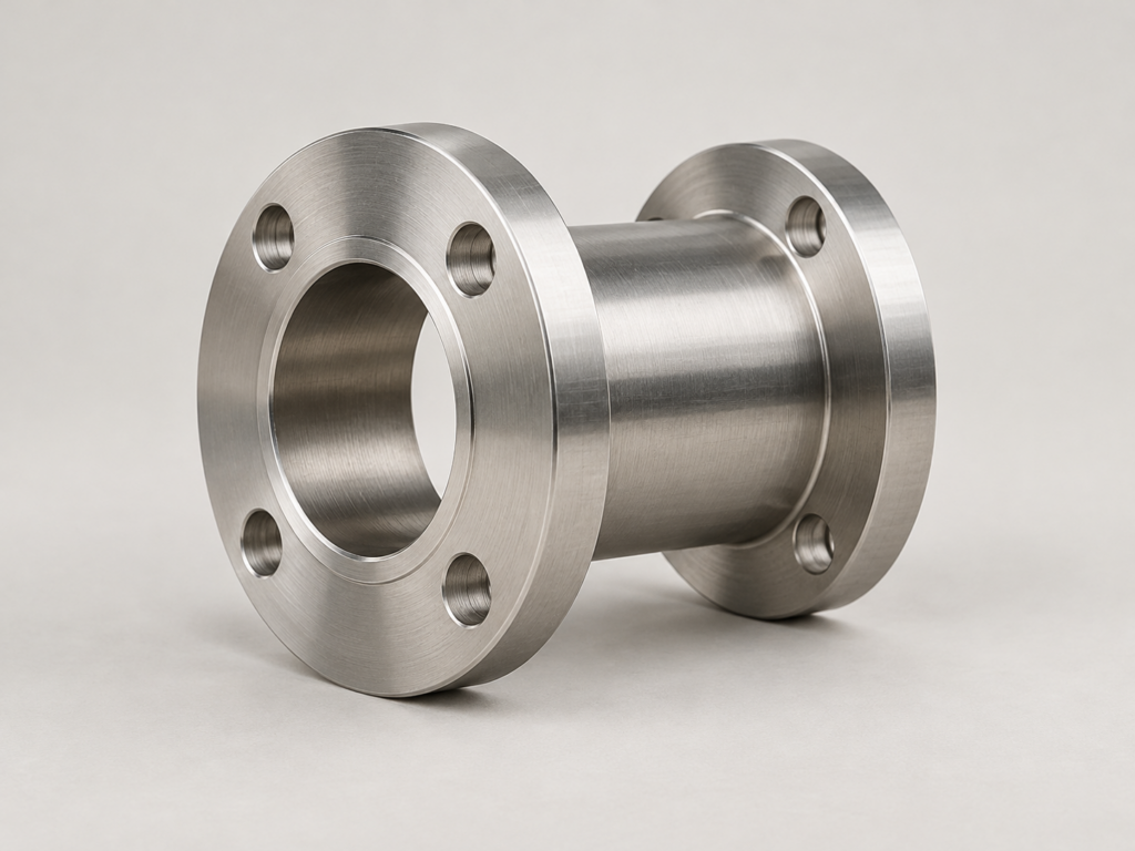
303 requires approval before replacing 304 or 316L. Passivation and final fit are grade-specific; 17-4PH also needs its specified heat-treatment state.
Specified mechanical parts where weight, corrosion or mechanical requirements call for titanium.
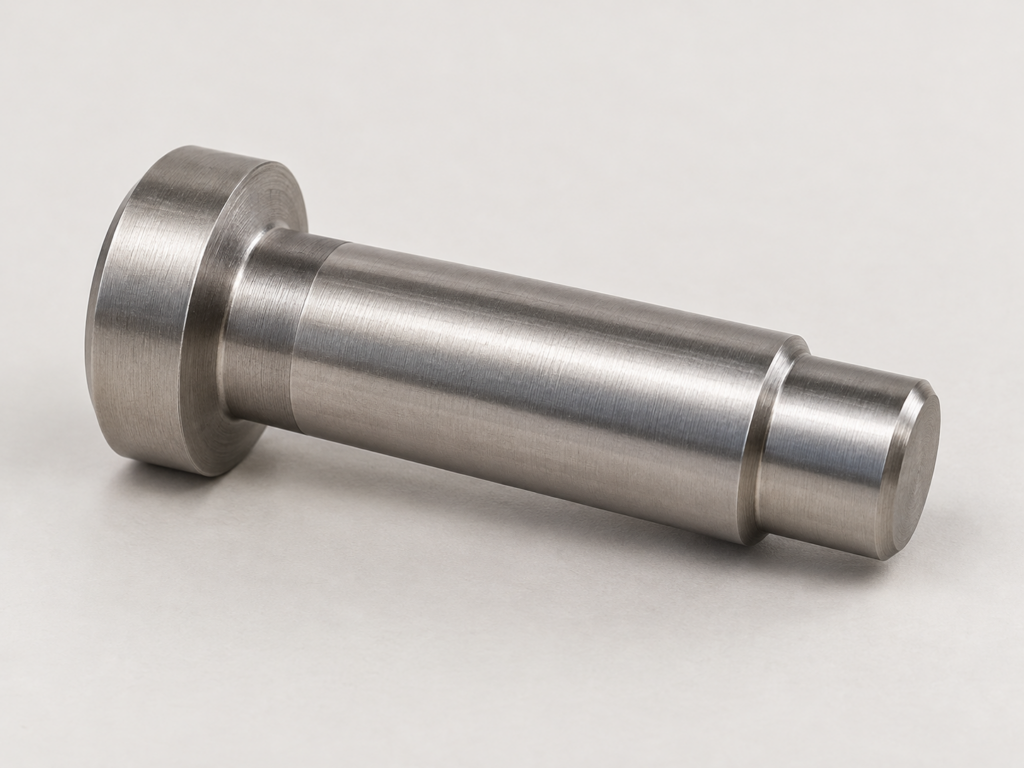
Availability, source, standard, state, geometry and documents are confirmed for the order. Implant or aerospace use requires separate qualification.
Functional prototype knobs and other rotational features.
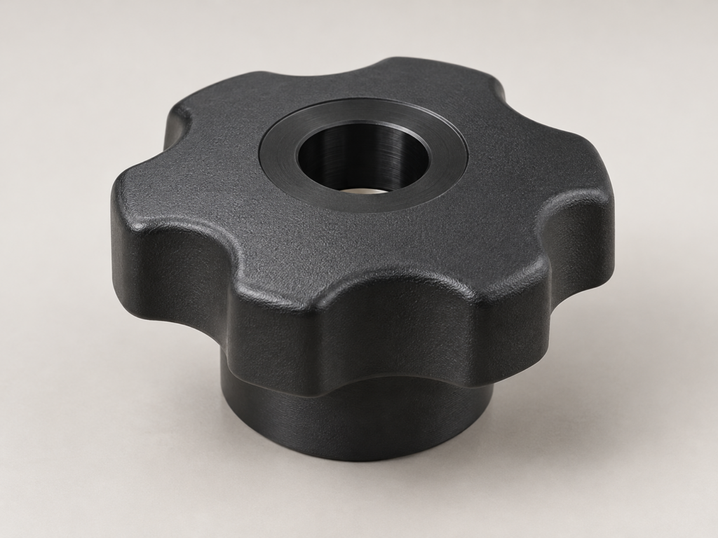
Appearance and dimensional stability depend on the specified machining stock. Injection-molding resin and FDM material have different material identities.
Clear prototype sleeves, windows and rotational shapes.
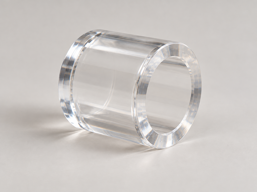
Surface, polishing and assembly conditions affect appearance and cracking risk. Optical-grade finished parts require a defined specification beyond transparent raw stock.
Protective prototype caps and rotational components.
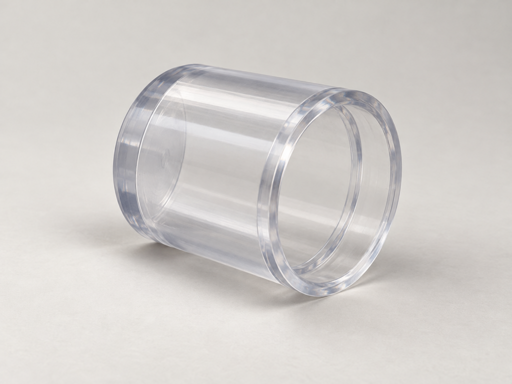
Residual-stress, surface and assembly requirements govern the finished part. Optical performance needs its own acceptance criteria.
Bushings, locating sleeves, spacers and sliding components.
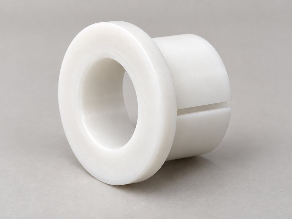
POM-C and POM-H are distinct grades; Delrin is a brand. Filler and measurement state matter for critical fits.
Rollers, sleeves and mechanical supports.
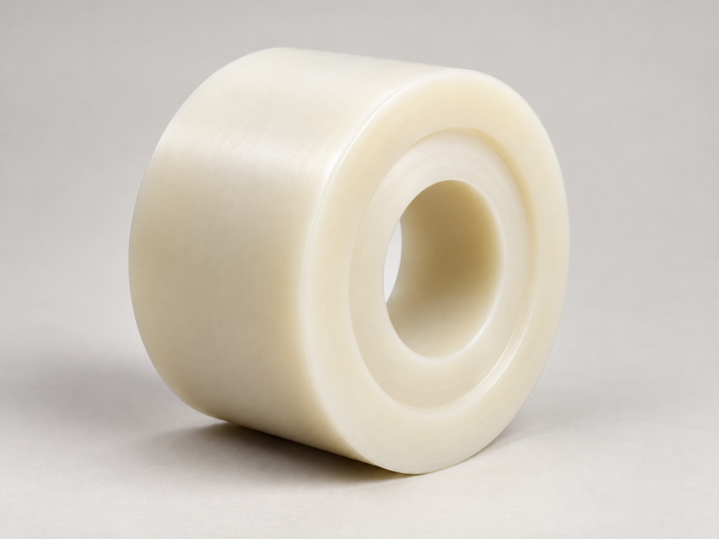
Moisture uptake and conditioning can change dimensions. Fit acceptance depends on the specified conditioning and moisture state.
Isolating, sliding and sealing geometries.
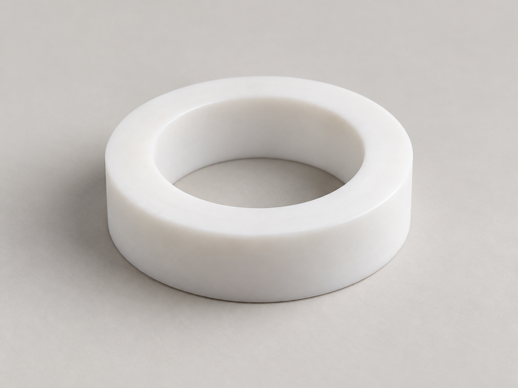
Filler, load, temperature and cold flow affect fit. A machined seal profile still needs application-specific sealing validation.
High-performance mechanical sleeves and threaded prototypes.
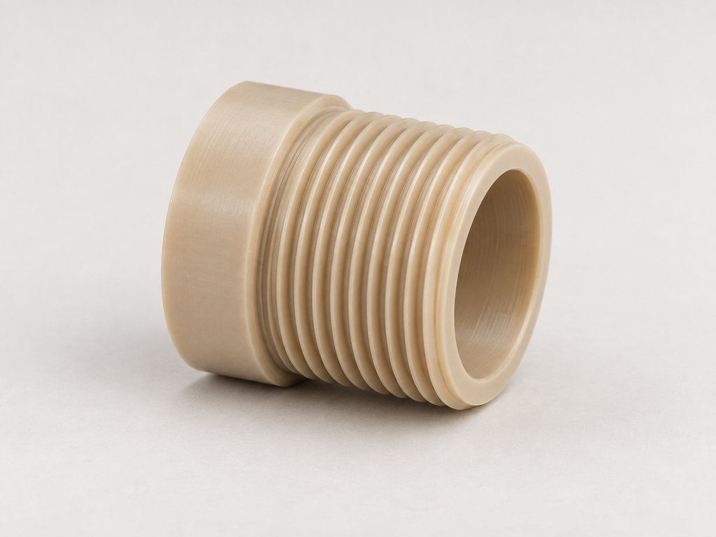
Brand, filler, environment and stock availability govern selection. Medical use requires the appropriate grade, documents and component qualification.
Caps and structural prototype geometries.
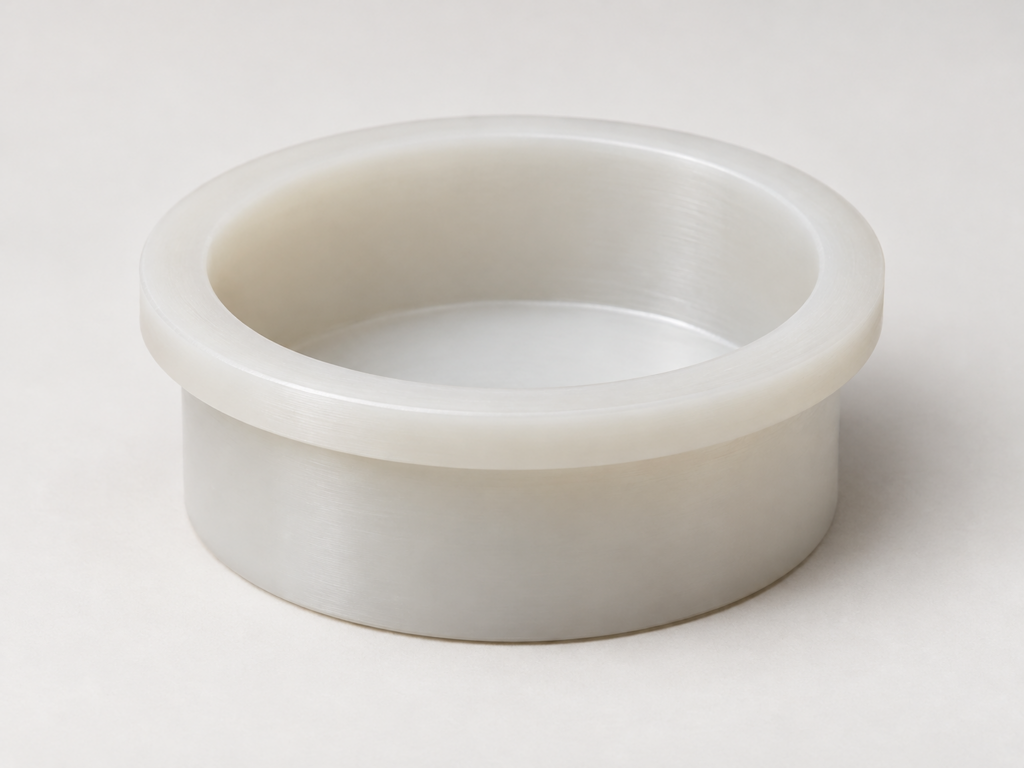
Wall structure, grade and function govern suitability. Living hinges and tight fits need their own design and material evaluation.
Guide sleeves, sliding spacers and device components.
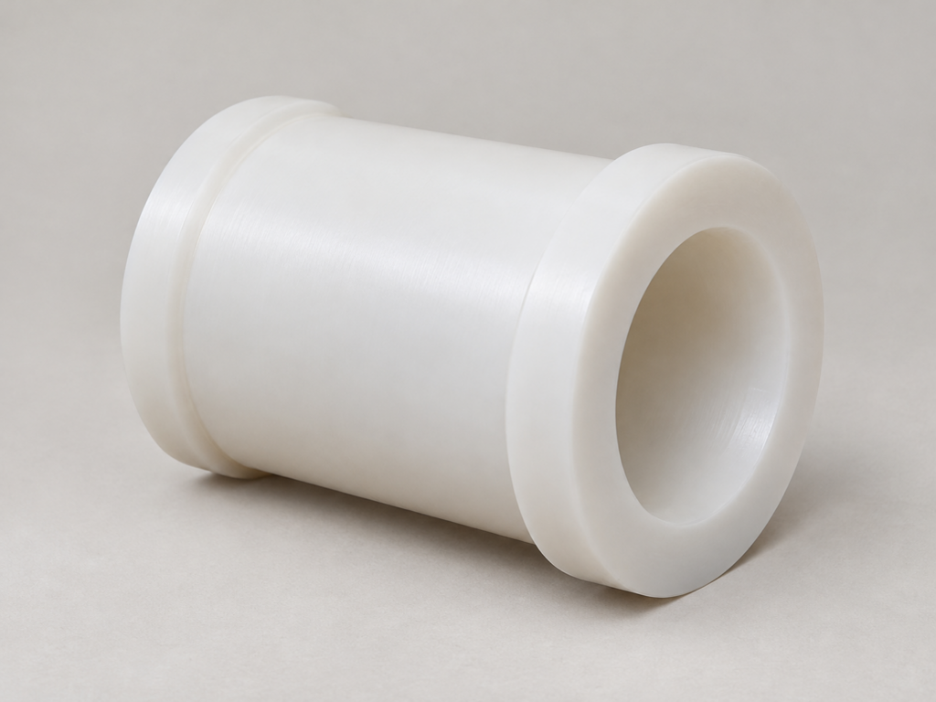
HDPE and UHMW-PE are distinct options. Long dimensions and tight tolerances require stability assessment for the selected grade and measurement state.
Mechanical or insulating collars with specified material requirements.
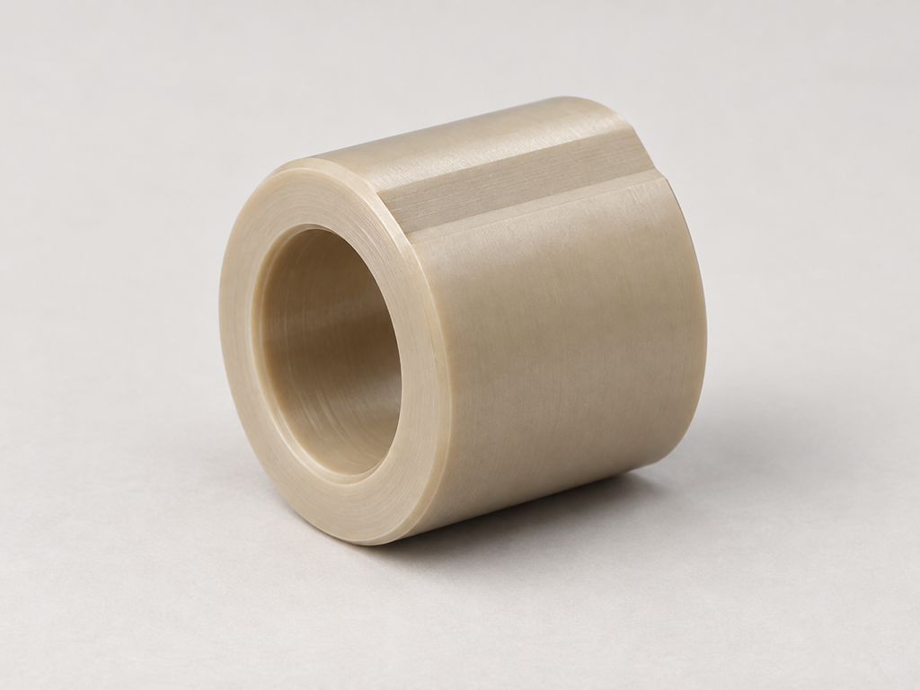
Material supply, stock form, geometry, conditioning and post-processing are confirmed before quotation. Dimensional requirements apply to the selected grade.
Stepped spacers and specified mechanical components.
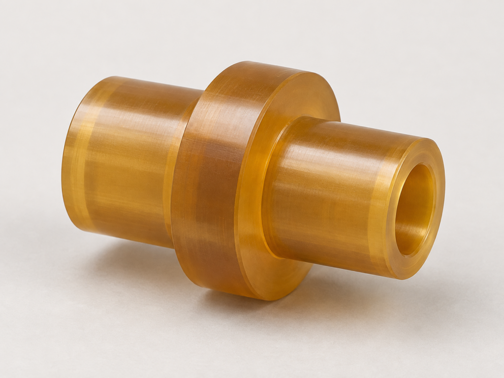
Selection depends on brand, stock form, environment and post-processing. Flame, medical or food-contact requirements need grade-specific documents and a defined use.
Sleeves and locating components with specified mechanical requirements.
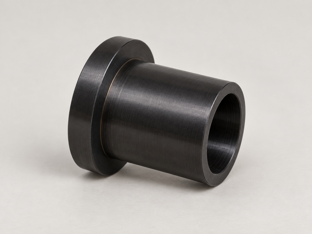
Material supply, processing, conditioning and measurement state are agreed for the design. Suitability depends on the selected grade and application.
Material examples — illustrations.
Surface Finishes That Preserve the Fit
We supply machined parts with the agreed surface finish and coordinate specialist treatments through selected partners. The functional surfaces and cosmetic faces can require different treatment.
As Machined and Deburred
For metals and engineering plastics when visible tool marks are acceptable. Burr limits, edge breaks and functional roughness follow the drawing; unmarked faces carry no automatic Ra requirement.
Mechanical Polishing
Reduces tool marks or provides an agreed appearance on suitable metals and polishable plastics. Texture direction and allowable edge change are specified separately; gloss and Ra are different requirements.
Bead Blasting
A consistent matte texture on specified aluminum, stainless steel or other suitable substrates. The agreed media and cosmetic faces determine the finish; critical bores, threads and mating surfaces are masked.
Painting
Specified color and cosmetic or protective finish on suitable metals and compatible plastics. Primer, color, gloss, adhesion and an appearance sample are agreed, with masked fits and inspection after coating.
Powder Coating
An agreed color and texture on suitable metal parts, with a specified coating system, mounting points and masked surfaces. Coating build affects clearances and differs from liquid painting.
Anodizing
For suitable aluminum alloys: ordinary anodizing for specified appearance and protection; hard anodizing for an agreed functional wear requirement. Final dimensions, color, sealing and masking form the specification. Coating thickness alone is not a universal fit-change calculation.
Stainless Steel Passivation
Specified cleaning and passivation for applicable stainless grades, with an agreed process and documents. The order’s identified critical features are rechecked after treatment.
Electroless Nickel
A specified plated surface on suitable metal substrates. The coating system, phosphorus or hardness requirements, masking and final fit define the order; subsequent heat treatment is a separate requirement.
Final-fit acceptance: Critical diameters and threads are accepted in the agreed after-treatment condition, with protected surfaces and reinspection dimensions identified before order release.
Surface finish examples — illustrations.
Applications for Custom Turned Parts
Parts for equipment development, assembly fixtures and mechanical interfaces, with material, documentation and acceptance requirements matched to their use.
Application contexts — illustrations.
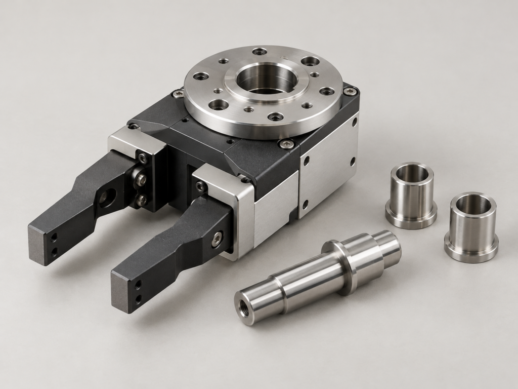
Robotics and Automation
Short shafts, locating pins, sleeves and spacers for fixtures, end-of-arm tooling and mounting interfaces. Mating dimensions, weight and stiffness requirements establish the part specification and baseline for the next approved batch.
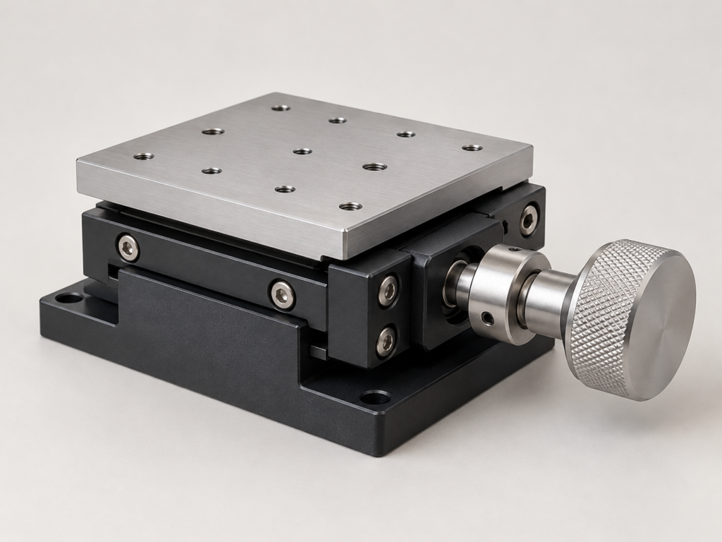
Electronics and Instrument Equipment
Adjustment knobs, connector details, sleeves and locating spacers for measurement and test equipment. Assembly interfaces, appearance and electrical contact surfaces determine the finish and its effect on fit.
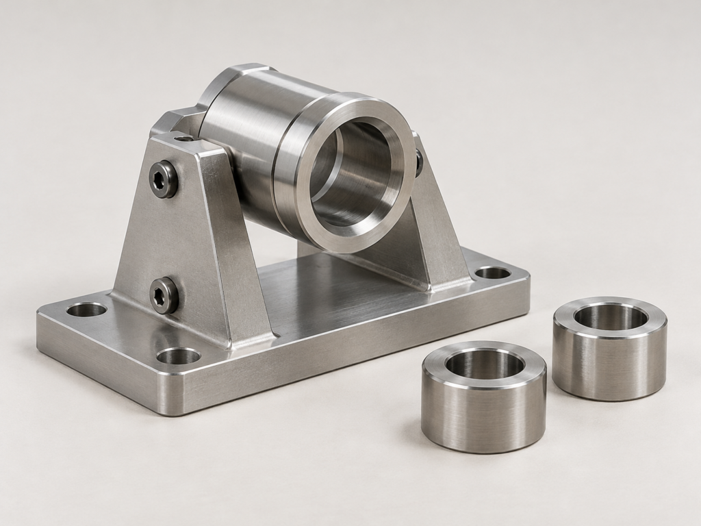
Medical and Laboratory Equipment R&D
Non-implant fixture sleeves, locating spacers and prototype mechanical components with specified traceability and documents. Patient contact, special cleanliness and final-use qualifications require project-specific review.
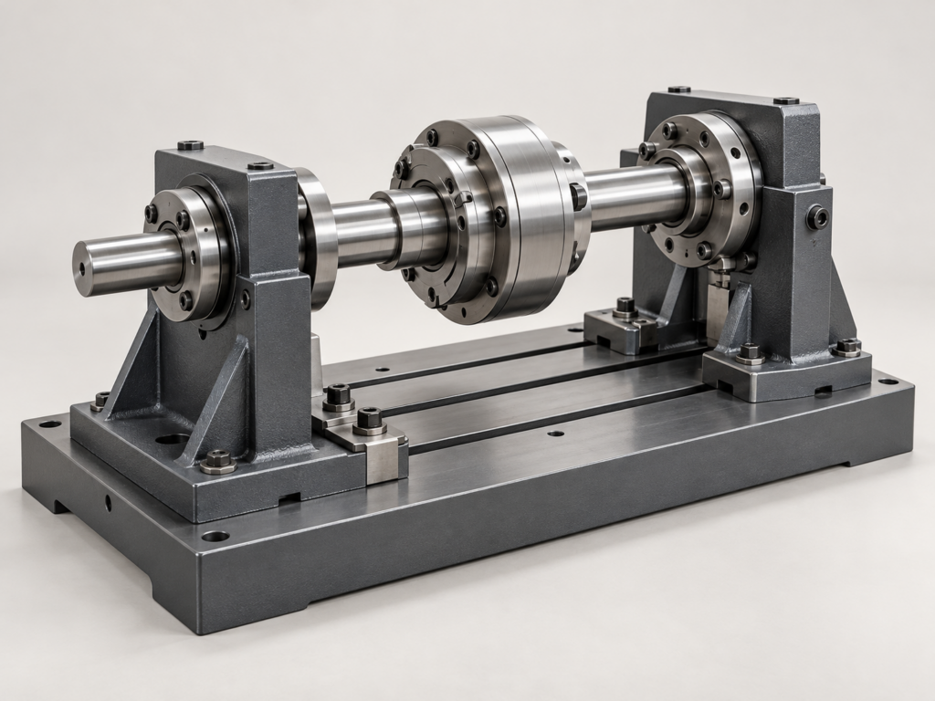
Automotive and New-Energy Development
Test-bench shafts, pins, sleeves and connection details for prototypes and development fixtures. Validation quantities and controlled drawing revisions guide the order; safety-critical serial production requires separate qualification.
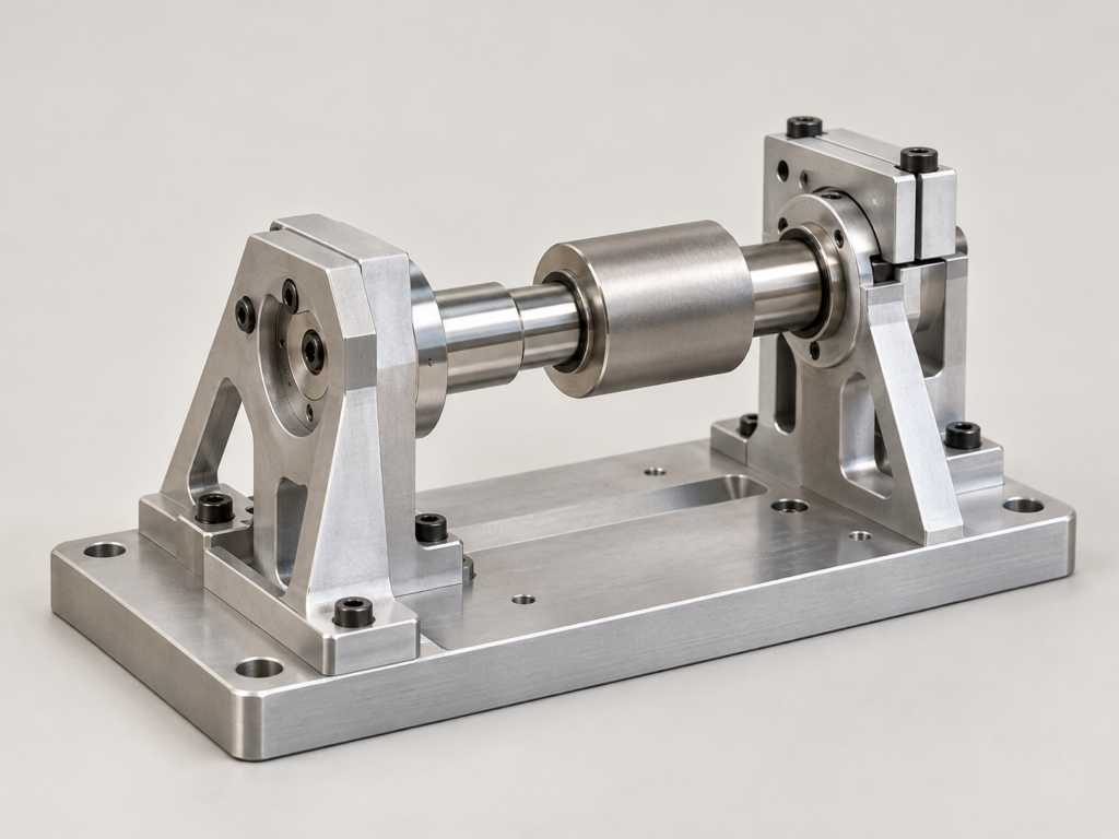
Aerospace-Related R&D and Tooling
Short prototype shafts, sleeves and spacers for assembly or test fixtures with specified material and documents. Flight-critical parts and customer approvals are evaluated separately.
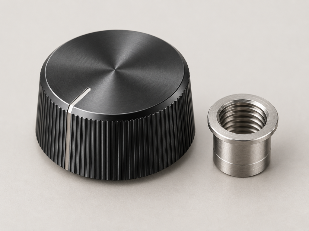
Consumer Products and Design Teams
Prototype knobs, threaded rotational fittings and small mechanical interfaces. Appearance, color, texture and fit matter alongside any difference between prototype stock and the intended production material.
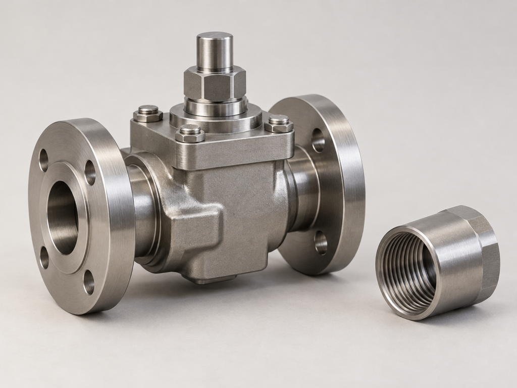
Industrial Machinery and Fluid Equipment
Shafts, sleeves, fittings and connectors for defined mechanical assemblies. Media, mating fit, wear surfaces and acceptance methods govern requirements; pressure, leakage and service-life performance need application-specific validation.
CNC Turning Tolerances and Surface Requirements
We quote the dimensions and surfaces that govern your assembly against the material, accessible geometry, datums and inspection method.
Dimensional and Geometric Requirements
| Feature | Capability basis | Conditions |
|---|---|---|
| General metal dimensions | Typically ±0.05 mm | Selected accessible, stable features with nominal dimensions of 3–100 mm; drawing requirements take priority |
| Precision metal dimensions | Down to ±0.01 mm after review | Typically no larger than 100 mm; matched datum, manufacturing and inspection methods |
| Finish-ground or fitted metal features | Down to ±0.005 mm by separate process review | Selected bores, shafts or planes with an agreed finishing and acceptance method; outside general turning precision |
| Plastic dimensions | Typically ±0.10 mm | Material, moisture, residual stress, temperature and structure affect results |
| Precision plastic dimensions | Down to ±0.05 mm after review | Stable material, small supported geometry and an agreed measurement state |
| Shaft roundness | 0.01 mm on selected small finished shaft diameters | Roundness is separate from size tolerance, cylindricity and datum-related runout |
| Runout | Drawing-specific | Identify the datum axis, controlled surface and acceptance method |
Surface Roughness
| Surface | Available requirement | Conditions |
|---|---|---|
| Machined functional surface | Ra 3.2 µm | Specified surface; visible tool marks remain |
| Fine-finished functional surface | Ra 0.8–1.6 µm | Accessible geometry; material and tool direction considered |
| Selected ground or polished metal surface | Ra 0.2–0.4 µm | Separate process and acceptance method; deep bores, arbitrary curved surfaces and plastics are outside this stated range |
General tolerances for unmarked dimensions are agreed before ordering. A general-tolerance standard does not assign one value to every nominal size.
Design Guidelines for Shafts, Bushings and Threads
Clear feature relationships let us machine and inspect the part you intend to assemble.
Workholding, Support and Mating Features
Allow sufficient stock and gripping length. Slender sections need support matched to their material and geometry. State the OD and ID limits and identify datums for runout; “tight fit” alone does not define an acceptance requirement.
Bores, Walls and Small Holes
Deep bores need tool reach and chip clearance. Local metal walls can be assessed from 0.8 mm, and plastic walls from 1.5 mm, where small structures can be supported. Shallow holes can be assessed from Ø0.5 mm; material, depth and breakthrough length determine feasibility.
Threads, Grooves and Shoulders
Internal and external threads are assessed from M2. State pitch, tolerance class, effective engagement, blind-hole clearance and gauging requirements. Groove widths, tool nose radii and shoulder relief must leave access for the cutting tool and the mating component.
Edges, Cross-Holes and Marking
Identify chamfers, edge breaks and burr-sensitive faces, including cross-hole breakouts inside a bore. Keep identification clear of functional fits. Part marking is available as an order option.
There is no universal length-to-diameter limit: the stock, support, tool access and required finish determine the suitable setup.
From One Prototype to Repeat Batches
We carry the approved drawing, material and inspection requirements from the sample into subsequent orders.
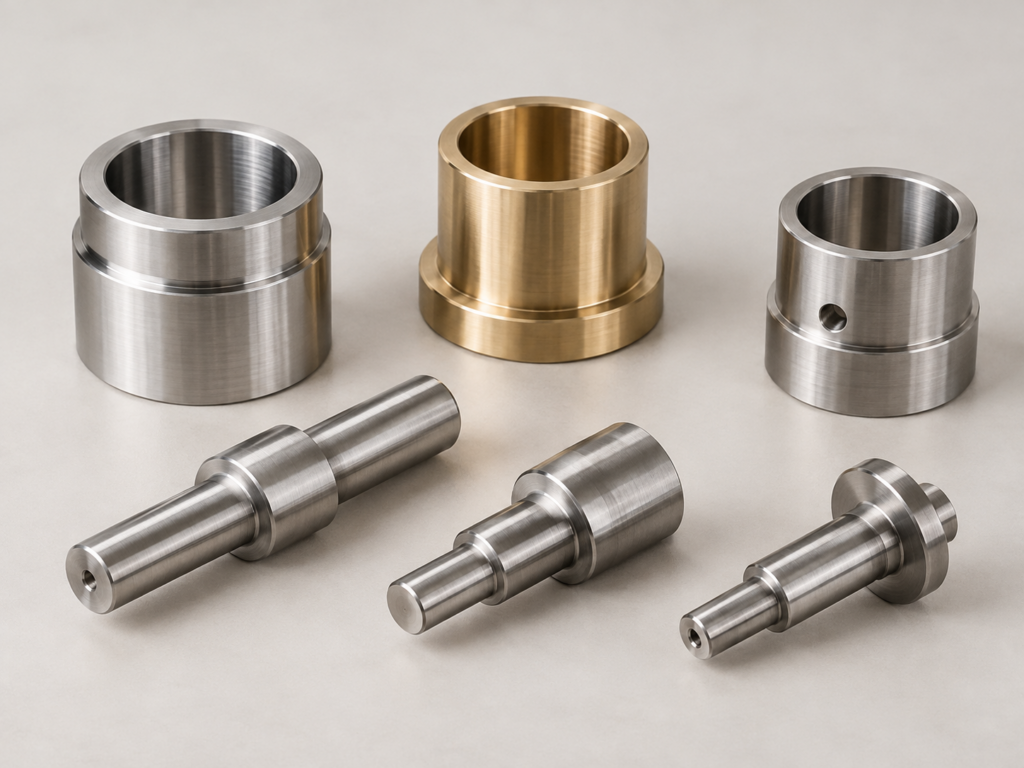
Prototype and Fit Check
CNC enquiries start from one piece, with common prototype orders of 5–20 pieces. Simple stocked aluminum or POM parts in quantities of 1–10, with normal tolerances and deburring, typically take 5–7 working days. More complex work, often 5–20 pieces, typically takes 8–12 working days; special material procurement and heat treatment are scheduled separately.
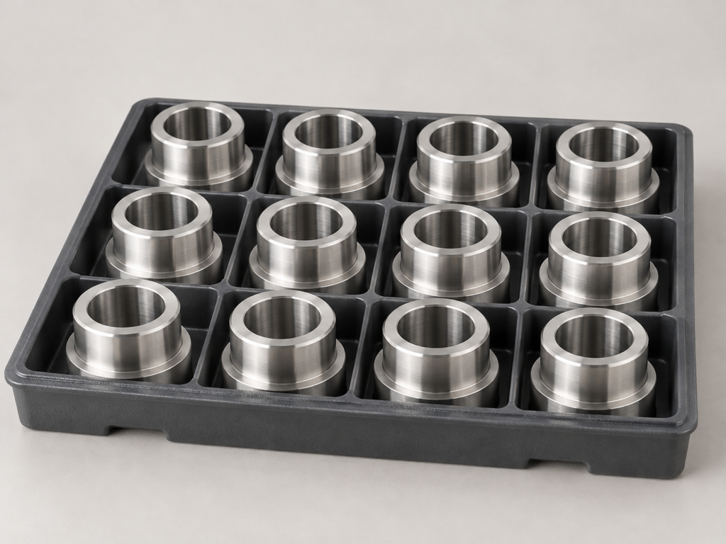
First Batch
Small batches commonly run 20–500 pieces. Approve the drawing revision and agreed sample or first piece before releasing production. The quotation defines the machining hours, inspection deliverables and schedule for that batch.
Repeat Supply
Repeat orders commonly run 100–5,000 pieces, subject to machining hours and scheduling. Approved repeat batches typically take 12–20 working days, with the approved revision, material and inspection requirements carried forward.
Quantity ranges overlap; they are examples of purchasing stages, not fixed minimum-order classes. Setup or material minimums can still affect individual projects.
Lead times start after requirements, order conditions and material are confirmed. Common specialist finishing adds 3–5 working days; customer approval and shipping are separate.
Prototype and batch part examples — illustrations.
How CNC Turning Makes Your Part
A lathe rotates the workpiece while controlled cutting tools produce the required profile around its axis.
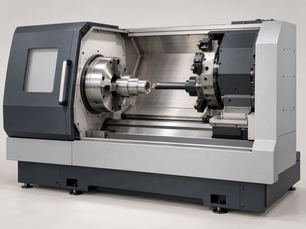
Turning and axial boring — illustration.
1. Rough and finish turning: Remove stock, face the ends and form outside diameters, shoulders and grooves.
2. Bores and threads: Drill or bore axial features and cut specified internal or external threads.
3. Side features: Use mill-turn or secondary milling for accessible holes, slots, flats and keyways.
4. Finish and check: Deburr, complete the agreed surface treatment and inspect the specified features.
A rotational body with diameters sharing a central axis favors turning. Prismatic parts, pockets and faces in multiple directions favor CNC milling. Some parts need both operations.
Inspection Planned Around Your Critical Features
First-piece, process and final checks follow the agreed drawing revision and critical features. Our resources include one CMM, two vision measuring systems, one roughness tester and suitable hand gauges.
| Requirement | Inspection approach |
|---|---|
| Outside diameter, bore and length | Suitable micrometers, bore or pin gauges and dimensional methods matched to the tolerance |
| Threads | Appropriate thread gauges and the specified inspection method |
| Datum relationships and runout | Agreed setup and method; CMM or other suitable equipment within its measurement capability |
| Surface roughness | Accessible measuring surface and a suitable roughness measurement method |
Instrument choice depends on range, access, probe, temperature and measurement uncertainty. Every part does not need every instrument; a selected ±0.005 mm feature requires a suitable acceptance method of its own.
Documents with Your Order
Key-dimension reports, available source material documents, a Certificate of Conformity and formal First Article Inspection can be agreed with the quotation. Routine first-piece checks and a formal FAI package are different deliverables. Full dimensional or 100% inspection is a separate scope.
Partner finishes are checked on return against the agreed treatment and applicable critical dimensions. Revision, material and inspection requirements remain associated with repeat orders.
Explore our quality and inspection arrangements.
Why Choose Great Machining for Turned Parts?
In-House Turning Execution
Your cylindrical body and accessible secondary features are machined by one in-house team responsible for the finished machined part.
Coordinated Specialist Finishing
Receive your machined component with specialist treatments coordinated through one project contact. Selected partners receive the material, finish and protected-fit requirements; treated parts are checked on return.
Direct Engineering Communication
Get a quotation that addresses tool access, critical fits and open drawing questions through direct discussion with the team responsible for machining your part.
Continuity for Repeat Orders
Reorder against the approved drawing revision, material and inspection requirements. Our team resolves drawing changes before releasing the next batch.
CNC Turning FAQs
Get a Quote for Your Turned Parts
Enough to start: Send a drawing, CAD file, sample or useful part description, plus quantity or development stage if known. We can identify the remaining questions with you.
Helpful for quotation: STEP or IGES plus a revision-marked PDF drawing; exact material grade and state; quantity levels; critical dimensions, tolerances, ID and OD fits, datums and runout; threads and burr limits; surface finish and masking; application or operating conditions; inspection documents; packing needs; delivery country and target date.
Our first human reply is within one working day. Straightforward CNC requests with complete requirements are usually quoted within one working day; complex requests generally need 2–3 working days. The first reply and the formal quotation are separate steps.
For an NDA or an open project question, contact us or email Great Machining.