CNC Milling Services for Equipment Parts
We machine custom plates, brackets, fixtures and housings to your assembly drawing. Great Machining combines in-house milling and dimensional inspection with coordinated specialist finishing, supplying prototypes and repeat parts with agreed materials, critical features and delivery scope.
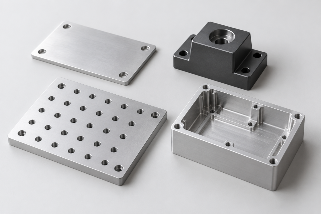
Equipment part geometry illustrations.
Milled parts for equipment assemblies
We machine metal and engineering plastic components for equipment builds, tooling and development programs.
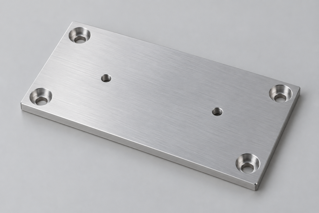
Plates and tooling bases
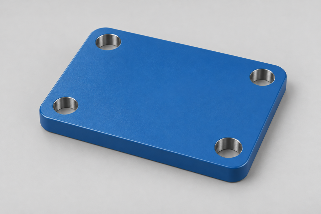
Mounting plates and bases with bolt patterns, pockets and reference faces for assembled equipment. Locating features establish the relationship to mating components.
Mounting plate illustration.
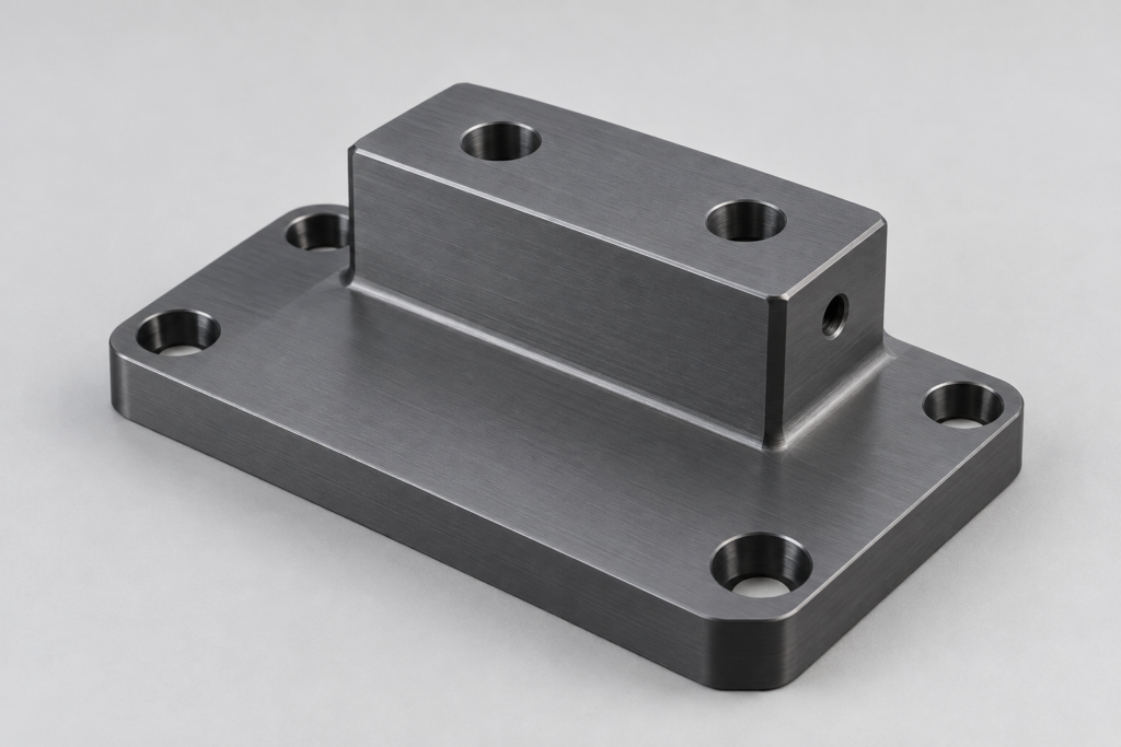
Mounts and brackets
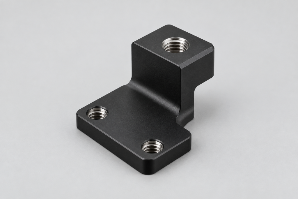
Sensor mounts, mechanical supports and brackets with features on different faces. Mounting faces and hole relationships can be defined around the installed position.
Stepped mount illustration.
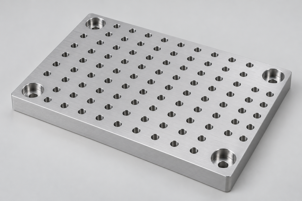
Fixtures and locators
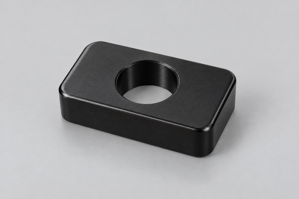
Fixture plates and locating components for positioning parts during assembly or inspection. Locating bores, threaded attachment points and accessible reference surfaces support the specified setup.
Fixture plate illustration.
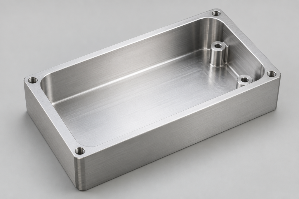
Housings and cavities
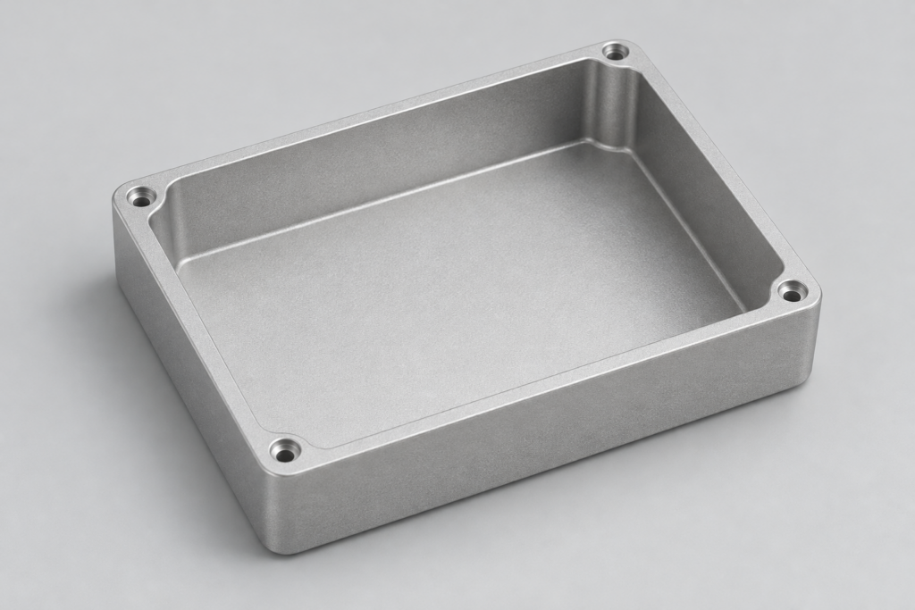
Instrument housings and pocketed components combining internal clearance with fastening and mating features. Cosmetic surfaces and functional interfaces can receive different finish requirements.
Pocketed housing illustration.
Milling access and setup options
Great Machining mills and dimensionally inspects your parts in-house, choosing setups around the geometry and assembly requirements. Rotating cutting tools remove material from secured stock along programmed toolpaths to create faces, pockets, contours and holes; drilling and threading complete the specified features.
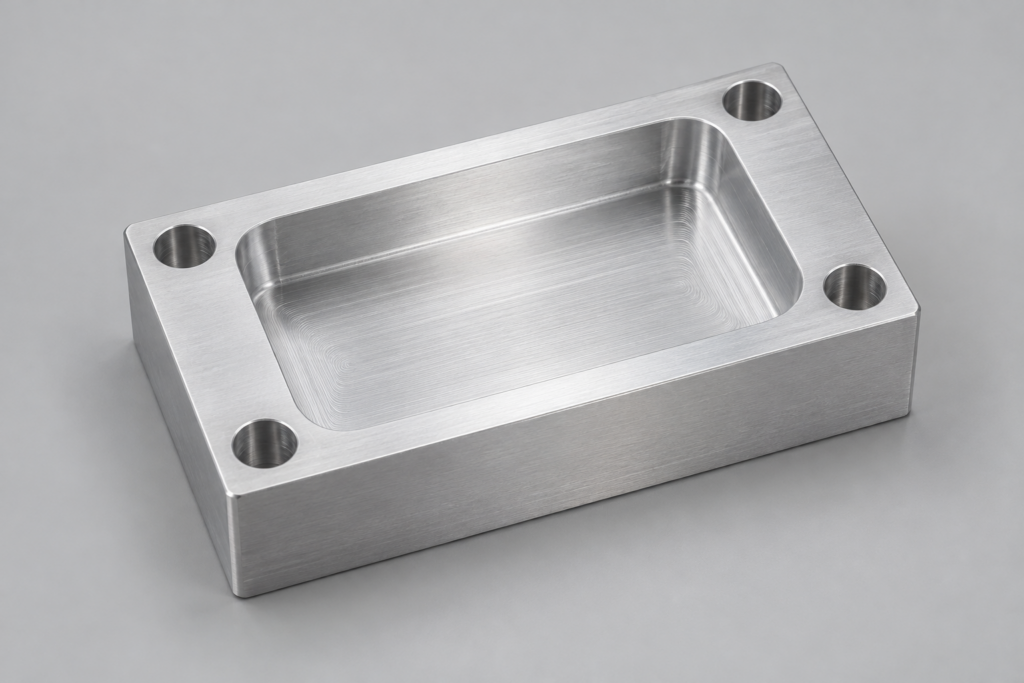
Three-axis milling — 18 in-house machining centers
For plates, blocks and housings with accessible faces and pockets, three-axis milling provides a direct machining route. The typical part envelope is up to 1000 × 600 × 400 mm. This describes the part envelope; stock, fixture space, tool reach and part weight require separate review and determine the usable size.
Top-access geometry illustration.
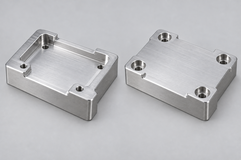
Five-axis machining — 4 in-house machining centers
Multi-direction mounting features, angled holes and accessible curved surfaces can benefit from a five-axis route that reduces re-clamping. Simultaneous or indexed machining is chosen for the part. The reference envelope is about Ø300 × 250 mm for clampable small and medium complex components, with angles and curves reviewed individually.
Opposite-face geometry illustration; setup depends on the part.
Re-clamping may still be appropriate where separate faces need access. The datum relationship between operations, usable clamping surfaces and inspection method matter alongside axis count. Size, reach and tight-feature capability are evaluated together in the quotation.
Prototype, first batch and repeat parts
Develop the fit, then carry the approved requirements into production. Our milling service supports prototype parts, first batches and scheduled repeat orders, with drawing revisions managed through the project.
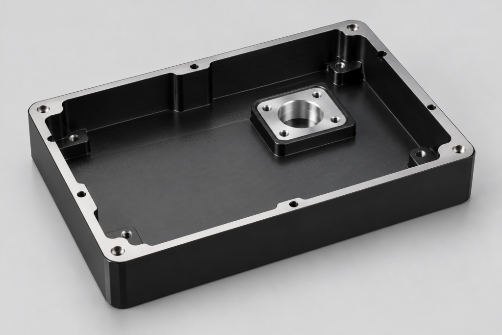
Instrument housings — locating fit after anodizing
12 pieces · prototype batch · 6061-T6 · 120 × 80 × 35 mm
An instrument-housing project combined a selected locating bore of Ø20.000–20.020 mm, 0.03 mm flatness across a 100 × 70 mm mounting face, and a black anodized appearance sample.
We separated roughing and finishing, masked the locating bore and specified contact areas, and checked the agreed features by CMM with post-treatment fit accounted for.
All 12 prototypes completed the agreed dimensional and fit checks.
Dispatch: 11 working days — 8 for machining, followed by 3 for specialist finishing and final inspection. A later 200-piece batch was planned.
Housing geometry illustration accompanying the project record.
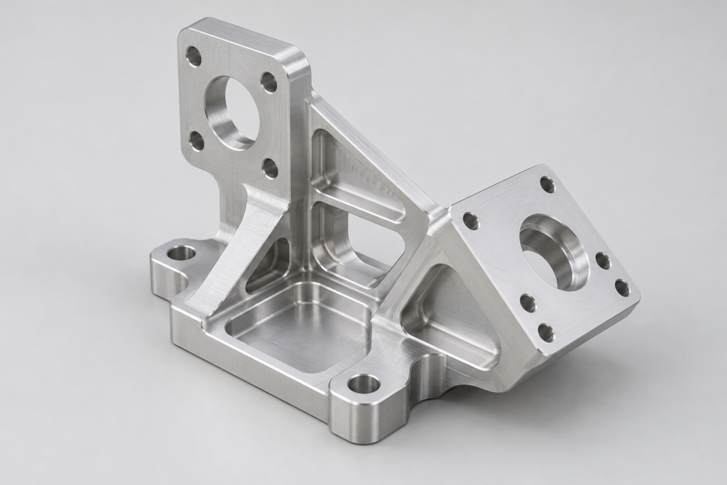
Robotic brackets — mounting features on multiple faces
20 prototypes · 7075-T6 · 160 × 100 × 65 mm
This robotic end-effector bracket required selected hole diameters to ±0.02 mm and hole position to Ø0.05 mm relative to A/B/C datums.
With customer approval, the model was adjusted in noncritical areas. A five-axis route produced the mounting features in multiple directions.
The 20 prototypes were supplied as-machined in 10 working days, including the agreed dimensional records.
Bracket geometry illustration accompanying the project record.
From trial fit to a released batch
Prototype: establish the controlled revision and features needed for the intended fit checks.
First batch: carry approved changes into the released material, finish and inspection requirements.
Repeat parts: retain the agreed revision baseline; changes to quantity, material or acceptance scope can change the manufacturing plan.
Typical manufacturing schedules
| Order stage | Typical manufacture | Applicable scope |
|---|---|---|
| Simple aluminum or POM prototypes | 5–7 working days | Available material; 1–10 pieces; ordinary tolerances and deburring. Special finishes add time. |
| Complex or multi-face prototypes | 8–12 working days | Usually 5–20 pieces. Special material procurement and heat treatment are agreed separately. |
| Repeat CNC batches | 12–20 working days | Approved revision and material confirmed; quantity and machining hours within the agreed schedule. |
Common partner finishing, such as anodizing, passivation or powder coating, typically adds 3–5 working days; special processes are quoted separately.
These periods start after files, technical requirements, order terms, necessary payments and material availability are confirmed, using the agreed production calendar. Customer approvals, extra drawing changes, transit and customs are separate. The quotation confirms the schedule for your order.
Materials for CNC milled parts
We supply milled aluminum equipment components alongside the metal and plastic options below, using the grade, condition and stock form specified for your part.
6061-T6 and 6082-T6 plate or bar suit housings, mounting plates and fixtures. 7075-T6 is an option for mechanical prototypes and structural components with higher strength requirements. The governing standard, temper, stock form and intended finish identify the required material; grades are quoted individually.
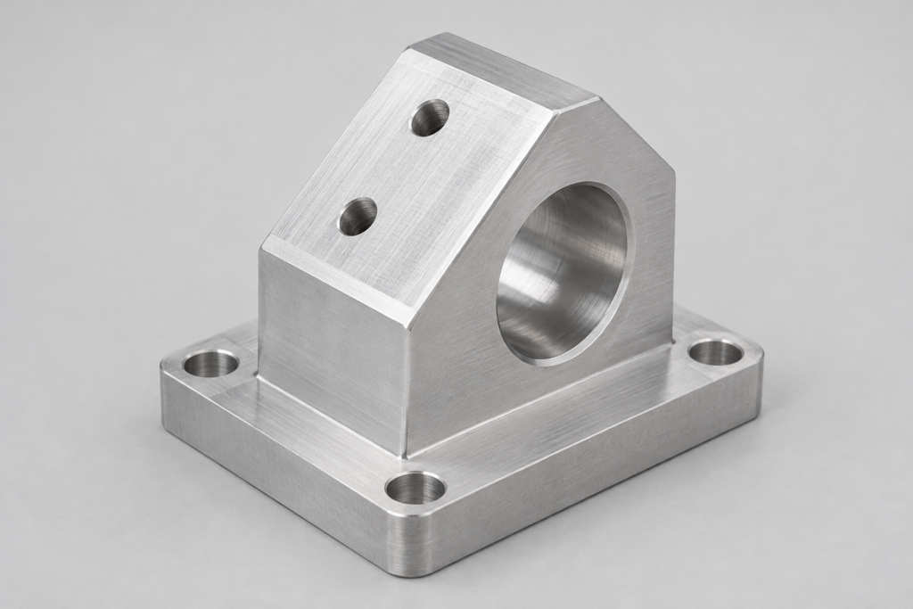
Aluminum mount illustration; appearance does not identify grade.
303 is primarily a bar-stock machining option; 304 and 316L can use specified bar or plate. For instrument components and fittings, the actual medium, welding and passivation requirements guide selection. The grades are not interchangeable.
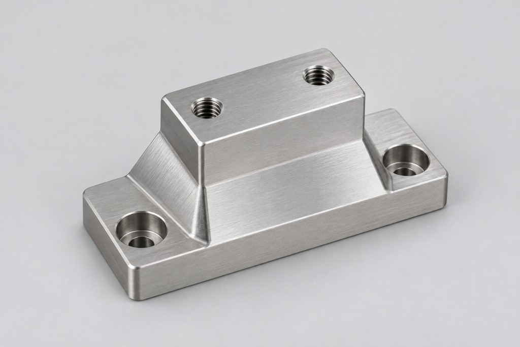
Stainless component illustration.
Bar and plate options serve supports, fixtures and mounting components. Material standard, target hardness, heat-treatment sequence and final dimensional machining must agree with the drawing.
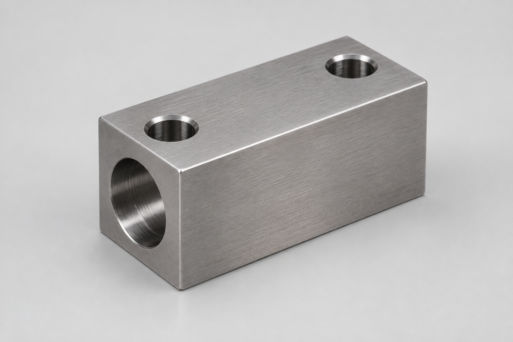
Steel locating block illustration.
Specified C36000 bar supports milled fittings and threaded components. The actual alloy must suit the intended medium and applicable requirements; this designation does not establish lead-free suitability.
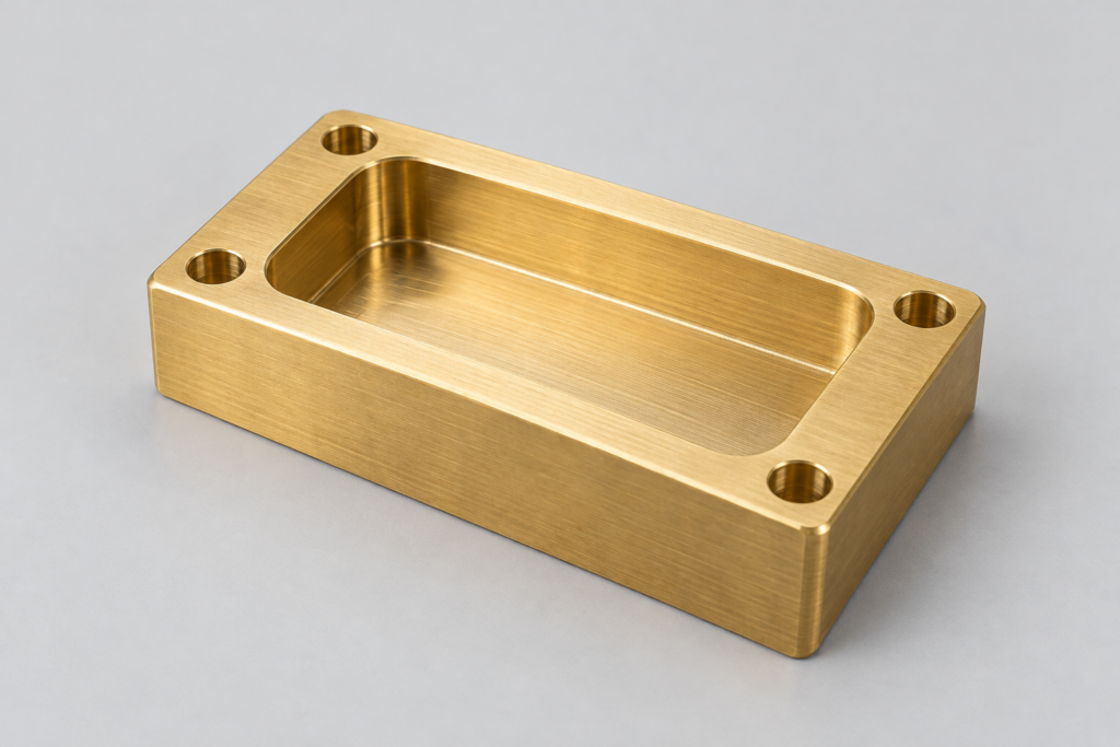
Brass component illustration.
POM-C and POM-H are distinct choices for guide blocks, sliding and locating parts. The required designation and dimensional measurement condition govern acceptance, especially for parts that must fit after conditioning.
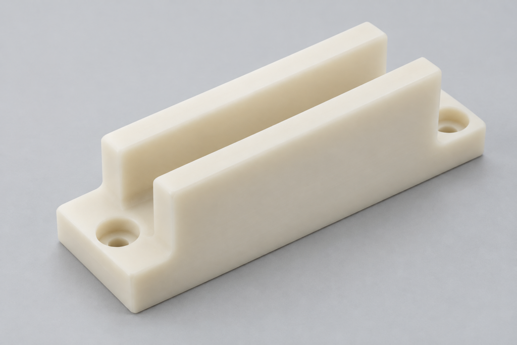
Polymer guide block illustration.
Surface finishes and functional faces
Source the surface your component needs, from visible tool marks to a specified coating. We coordinate specialist finishing through production partners; the quotation defines the process and acceptance requirements. Drawing-defined cosmetic areas, mating faces, threads and contact points keep treatment focused on the assembled part.
An as-machined surface suits parts where function takes priority over a uniform cosmetic appearance. Tool marks remain, with their acceptable direction defined on visible or contacting faces. Deburring, edge breaks and drawing-specified texture form part of the requested condition. Functional and cosmetic surfaces can carry different requirements, including faces that remain uncoated after another area is treated.
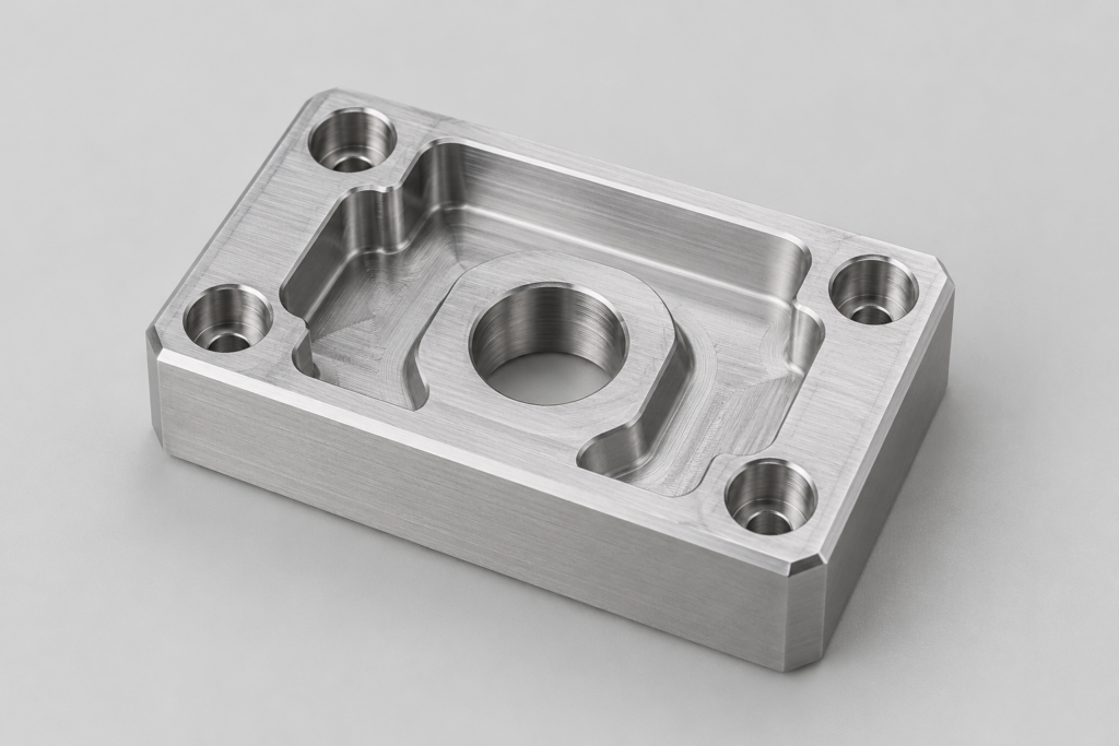
Illustrated as-machined appearance.
Sanding or polishing provides an agreed visible texture or polished appearance on accessible surfaces. An appearance sample and grain direction make the request more precise. These processes remove material and can soften edges; defined edges and fit features need protection where required. Mirror appearance and measured surface roughness are separate acceptance requirements.
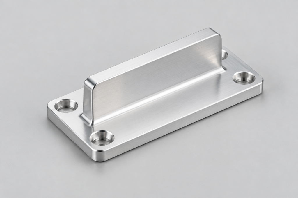
Illustrated sanded and polished appearance.
Sandblasting and bead blasting offer different media and texture choices for suitable substrates. Specify the media, process and an agreed appearance sample; their results are not interchangeable. Threads, locating bores and mating faces may need protection. When a coating follows, the surface preparation and treatment sequence must suit that coating system.
Illustrated bead-blasted texture.
A specified liquid-paint or powder-coating system supplies the required color, gloss and texture. Liquid paint and powder coating need different substrate and process compatibility checks. The appearance reference, preparation, masking and rack or contact locations define the finished result. Mating interfaces need final dimensions that account for the selected system, especially around fasteners and assembly clearances.
Illustrated painted appearance.
Standard or hard anodizing is available for a suitable aluminum grade and condition. The requested system, color or appearance sample, sealing requirements and electrical contact locations define the treatment. Locating bores and mating faces may need masking or a final-fit allowance. Post-treatment acceptance belongs with the finish requirement, as in the instrument-housing project above.
Illustrated anodized appearance.
For an e-coating requirement, send the coating specification and substrate so we can assess a suitable specialist route. Recesses, contact points and masked areas need explicit requirements, together with any coating records. Mating features need a defined dimensional acceptance condition after treatment. The requested coating system and part geometry determine the quotation; an appearance reference alone cannot define the process.
Illustrated e-coated appearance.
The specified nickel-plating process determines more than appearance. Our coordinated electroless-nickel option is assessed for suitable metal substrates; other nickel routes require their own confirmation. Substrate preparation, coating allowance on mating faces and threads, masking and any later heat treatment affect the finished component. The required coating and dimensional inspection records establish acceptance of the treated part.
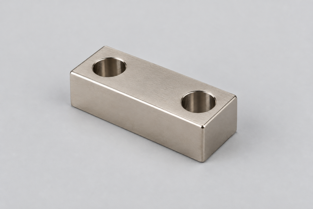
Illustrated nickel-plated appearance.
Define tolerances around assembly features
We machine and inspect against the agreed drawing, concentrating acceptance on the features that establish fit. The capabilities below apply to selected features under their stated conditions. The drawing and agreed general-tolerance standard and edition govern the order; the tightest values and largest envelopes are not automatically combined.
| Feature or surface | Capability | Conditions and acceptance basis |
|---|---|---|
| Ordinary metal dimensions | Typically ±0.05 mm | Selected stable, accessible features with nominal sizes of 3–100 mm; drawing tolerances take priority. |
| Precision metal dimensions | May reach ±0.01 mm | Selected features generally no larger than 100 mm; datum, machining route and measurement method reviewed for that feature. |
| Ordinary plastic dimensions | Typically ±0.10 mm | Selected features; material, moisture, residual stress, temperature and geometry affect the result. |
| Precision plastic dimensions | May reach ±0.05 mm | Stable material, small supportable geometry and an agreed measurement state. |
| Functional-face flatness | 0.03 mm on a selected 100 × 100 mm face | Complete measured extent, support and measurement state agreed. Larger areas require separate assessment. |
| Specified machined functional face | Ra 3.2 µm | Tool marks remain; this applies to the specified face, not every unmarked surface. |
| Reachable finish-machined face | Ra 0.8–1.6 µm | Material, shape, tool and cutting direction determine feasibility on the accessible functional surface. |
Locating, mounting and threaded features
| Assembly feature | Drawing and datum requirement | Measurement and treatment stage |
|---|---|---|
| Locating bore | Bore size and fit; relationship to the mating or reference feature | Size-measurement method and check stage agreed, including any masking and post-treatment fit. |
| Hole pattern | Position relative to the named datum system | Defined datum setup and a suitable coordinate or optical method; acceptance at the specified final finish state. |
| Mounting face | Flatness extent and any orientation to a named datum | Support and measurement method specified; acceptance before or after treatment as agreed. |
| Threads | Specification, tolerance class, effective depth and blind-hole bottom | Agreed thread gauges or other inspection, with the final coating condition identified. |
In-house dimensional inspection
1 CMM · 2 optical measurement systems · 1 surface roughness instrument, supported by task-appropriate gauges.
CMM measurement supports coordinates, datums and geometric requirements within its range. Optical systems suit small contours, hole positions and optically accessible features; roughness measurement requires a reachable surface. Instrument range, probing or access, temperature, method and measurement uncertainty must suit the actual acceptance requirement.
Documents supplied with your order
Parts ship with labels and a packing list identifying the relevant part number, revision, quantity and batch.
Reports and records: we supply key-dimension reports, available source material documents, an order-specific CoC, project first-article records and specialist-process records as agreed in the quotation. Material document availability and certificate level depend on the source.
Separately scoped: full dimensional reports, individual reports and full inspection of every piece.
A CoC records conformity to the order; it is not a third-party test certificate.
Design details that affect milling
A few geometry choices can change tool access, setups and machining time. Our engineering team can discuss these details against the required function before the design is released.
CNC milling questions
Request a quote for your milled parts
Get custom equipment components with the machining, finishing and inspection your order requires.
Enough to start: send a drawing, CAD file, sample details or useful part description, plus quantity or project stage when known. Open material or process questions are welcome.
Helpful for quotation: a controlled PDF and STEP or IGES model, material grade and condition, quantities, critical dimensions, datums and tolerances, surface finish and masking. Operating or application conditions, document and packing needs, destination and target date help define the complete order.
We review the requirements and return a human engineering quotation with the proposed scope and schedule.