Industrial Equipment Machined Parts
Custom machine components for new equipment, planned modifications and repeat orders. Great Machining makes plates, connection blocks, mounts, shafts, sleeves and engineering plastic parts from your drawings.
Get machined components with the material, functional surfaces and inspection records agreed for your order. Our in-house team handles CNC machining and dimensional inspection, with specialist finishes arranged through selected production partners.
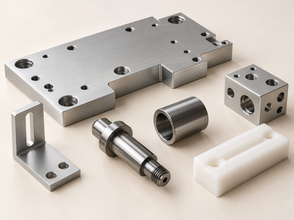
AI illustrations show representative component shapes and possible assembly locations. They are not photographs of delivered parts or customer equipment.
Find components for your equipment assembly
We supply machined parts for special purpose machinery and other equipment projects. Start with the component you need to locate, connect, support or guide.
Plates and connection blocks
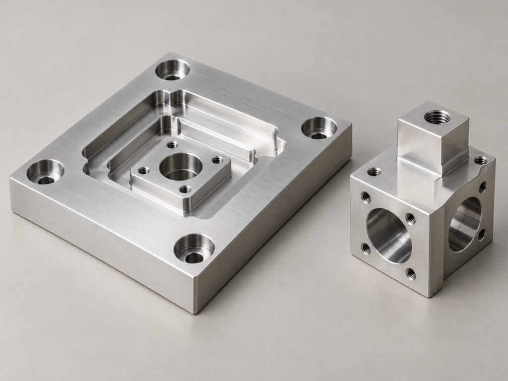
Baseplates, fixture plates and structural blocks provide mounting interfaces for equipment modules. Milled pockets, hole patterns, bores and tapped features are made to the approved drawing; identify the faces and features that establish the assembly position.
AI illustration — a pocketed plate and a separate bored connection block.
Mounts and adapting parts
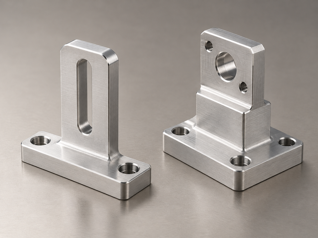
Sensor mounts, camera brackets, risers and interface adapters connect a device to the surrounding structure. Include the mating pattern, orientation and any adjustment slots, together with the faces that must remain controlled after finishing.
AI illustration — a slotted bracket and a stepped mount with a round interface bore.
Shafts, sleeves and spacers
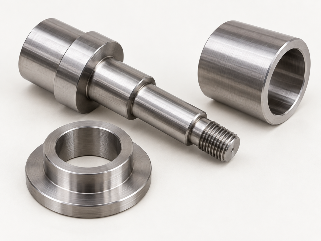
Turned components support locating, spacing and mating functions. Define the fitted diameters, shoulders, threads and required surface condition separately; a nominal diameter alone does not define the accepted fit.
AI illustration — a shoulder shaft, cylindrical sleeve and flanged spacer.
Polymer guides and contact parts
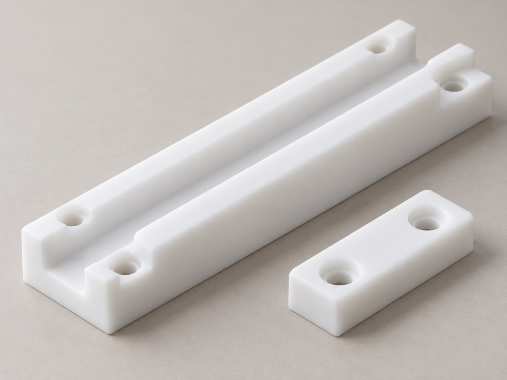
Machined guide blocks, support pads and locating pieces can be supplied in specified engineering plastics. Give the actual grade and the contact, mounting and measurement requirements; different polymers and material conditions need separate assessment.
AI illustration — a white channel guide and a two-hole support pad.
For robotic tooling and automation interfaces, explore Robotics and automation parts.
Equipment-use example: 316L sleeves
For an industrial automation OEM project, we supplied a 100-piece batch of 316L sleeves with an 18 mm outside diameter, 10 mm bore and 45 mm length. The drawing specified an outside diameter of 18.000 ±0.010 mm, a bore of 10.000–10.020 mm and Ra ≤0.8 μm on selected fit surfaces.
The route combined turning and finishing of the mating surfaces, controlled deburring, passivation and rechecking of the agreed features. Fit diameters, length and surface requirements were recorded separately.
Support for development, modification and repeat supply
New equipment development
Use prototypes to check your component’s fit and assembly interfaces before releasing a larger batch. Provide the current model or drawing and the features you want to evaluate. We raise manufacturing questions for your approval; the machine’s function and validation remain with your engineering team.
Planned equipment modifications
For a replacement or adapted component, identify the existing mating interfaces, the controlled reference and the changes required. A worn part or photograph may start a discussion, but missing dimensions, material identity and acceptance requirements must be resolved before manufacture.
Repeat orders and scheduled releases
Confirm the drawing revision, material, finish and inspection scope for each release. For planned supply, agree release quantities, dates, material purchasing and any stock responsibility. A previous order does not automatically authorize a changed design or a different material.
Connect the assembly interface to the delivered part
The illustrated arrangement shows how a plate, uprights, shaft, polymer block and sensor mount can occupy different positions in an assembly. Your drawing defines which relationships the supplied components must preserve.
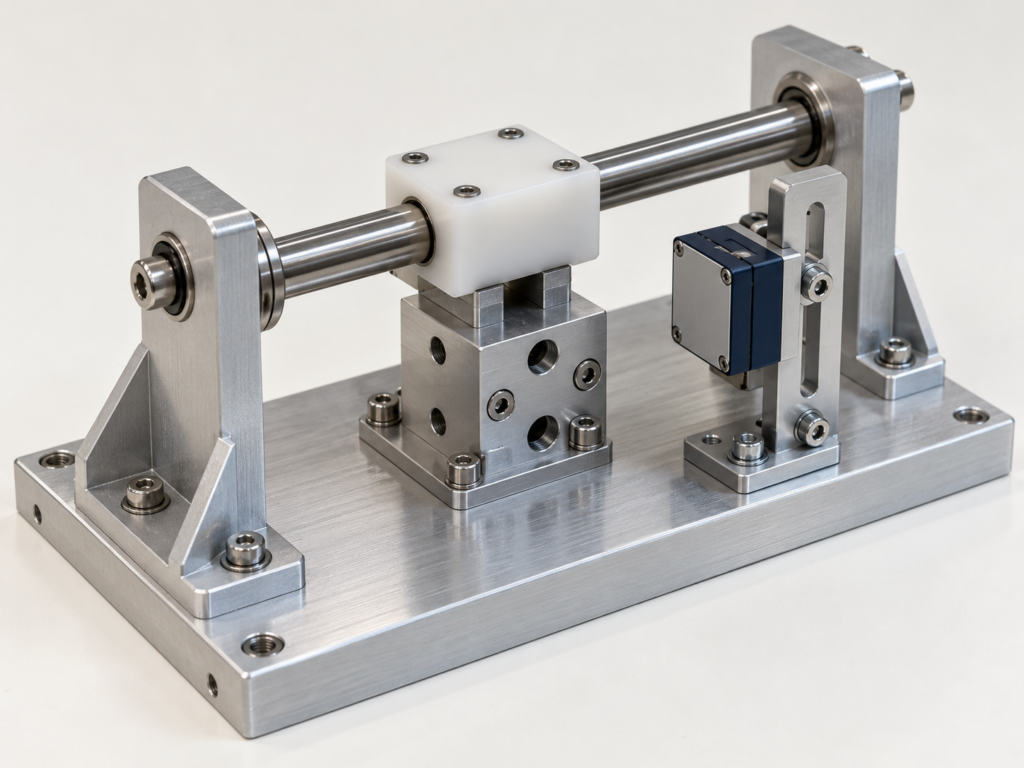
AI illustration — possible component locations in a generic fixture arrangement, not a customer installation or a validated machine design.
Establish the locating reference
Identify the mounting face, hole pattern and orientation that locate the component. State datums and the critical relationships between features, including any flatness or position requirements. We review these against the machining and inspection route.
Define the mating condition
For a shaft and bore, specify each accepted size and the relevant surface requirements. For an adjustable mount, distinguish clearance slots from locating features. State whether the final acceptance applies before or after a coating or heat treatment.
Agree the delivery condition
Specify whether the order covers separate parts, installed inserts or an agreed mechanical subassembly. A subassembly needs a parts list, purchased-item identities, assembly requirements and checks. Component manufacture does not include complete-machine design, controls, commissioning or system safety validation.
Manufacturing routes for custom machine components
Milling and multi-face machining
CNC milling produces the pockets, faces and hole patterns in plates, blocks and brackets. Multi-face, five-axis or separate setups are selected for the actual geometry and datum relationships. Tool access, support and the inspection method affect which features can be made together.
Turning and selected finishing operations
CNC turning suits shafts, sleeves and spacers; mill-turn work can combine rotational features with appropriate cross-holes or flats. Selected grinding or other finishing operations are assessed where the fit or surface requires them. Limiting tight tolerances to the functional features avoids unnecessary machining and inspection work on other dimensions.
Coordinated additional processes
Where a component is better suited to sheet metal, printing or moulding, we can assess a route through selected production partners. Specialist surface treatment and testing are also arranged to the agreed scope. Your quotation identifies the manufacturing route and deliverables; restrictions on manufacturing location or subcontracting should be raised before acceptance.
Material choices for equipment components
Aluminium plates, blocks and mounts
6061-T6 and 6082-T6 are separate grade choices for machined components; confirm the required standard, temper and stock form. 7075-T6 can be assessed for specified structural parts. The drawing and intended finish govern the choice, with no automatic substitution between grades.
Aluminium CNC machining covers grade, machining and part requirements in more detail.
Steel locating and support parts
Carbon and alloy steels such as 1018, 1045 and 4140 can be assessed for shafts, fixtures and support components. State the material standard, hardness condition, heat treatment and surface protection. The sequence must account for the final dimensions required.
Stainless steel components
303, 304 and 316L are assessed as distinct grades. Confirm the environment, material form, joining requirements and any cleaning or passivation specification. Ease of machining does not authorize replacing a grade specified for the component’s use.
POM guides and locating pieces
Specify POM-C or POM-H and any required brand or grade. Agree the measurement condition for dimensional acceptance, especially where temperature, material state or a supported shape affects the result. Other engineering plastics are reviewed against the particular component requirement.
Choose finishes around material and function
As-machined and deburred parts retain machining marks, with edge treatment and functional surface requirements defined on the drawing. For suitable aluminium, anodizing can be assessed with the colour, protected zones and final fit agreed. Stainless passivation is specified separately from an appearance texture; steel protection is selected for the material and intended conditions.
Mark fitted bores, threads, contact faces and visible surfaces that need specific treatment or masking. Coating thickness is not a universal conversion for dimensional change. We confirm the processing and final inspection scope with the specialist route.
Surface finishing options explains the treatment choices and the details to include in an enquiry.
Inspection and records for your component order
We confirm the drawing revision, material and critical features before production. If a 2D drawing and 3D model disagree, the controlled version is clarified first. First-piece, process and final checks follow the agreed inspection plan, including relevant features after specialist processing.
Key-dimension reports, available material documents, conformity statements and formal first-article records can be included as specified in the order. Routine first-piece checks and a formal FAI are different deliverables; full-dimensional or individual-part inspection is a separate scope. Part labels and packing information connect the delivery to the agreed part number and revision.
Quality control and inspection describes inspection methods and document options for supplier qualification.
Industrial equipment parts questions
Discuss your next equipment component
Start with a drawing, CAD file or useful description and tell us where the component will be used. Add the quantity and whether it is for development, a planned modification or repeat supply.
Material and finish if known, critical mating features, document requirements, delivery country and target date help us refine the quotation. We return a part-specific manufacturing scope, price and schedule for you to review.
Keep initial website enquiries non-confidential. Agree the NDA and transfer arrangements before sending protected files.