Scientific Instrument Machining
Custom sample holders, test fixtures, internal supports and housings for laboratory and test equipment. We machine metal and engineering plastic components from your drawings, supporting prototypes, small batches and repeat orders.
Our in-house team handles CNC machining and dimensional inspection. Specialist finishing is coordinated through selected partners to the agreed specification.
Images are AI-generated illustrations of component types.
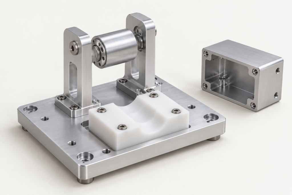
Parts for Laboratory and Test Equipment
We supply laboratory equipment parts individually or as a multi-part package, with simple mechanical assembly and inserts where specified.
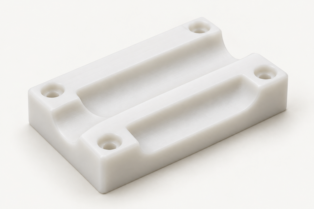
Sample holders and locating blocks
We machine sample holders with custom pockets, grooves and locating features, to specified mating geometry, contact surfaces and agreed refitting checks.
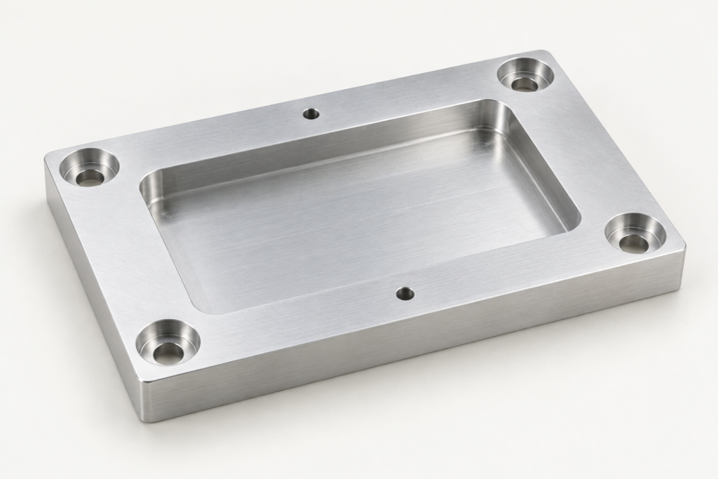
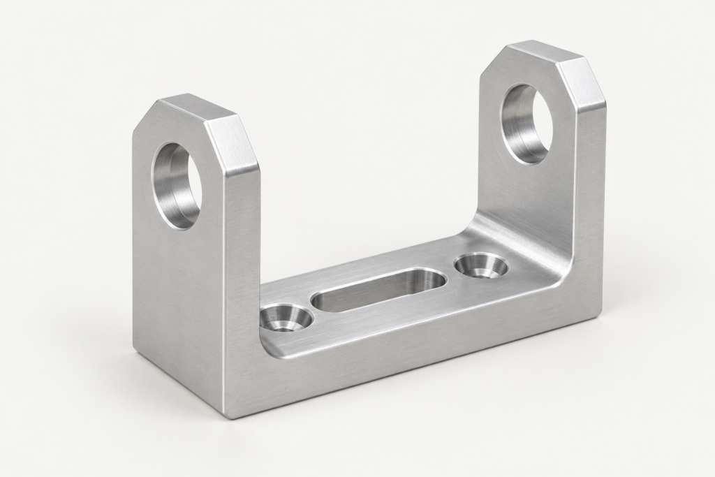
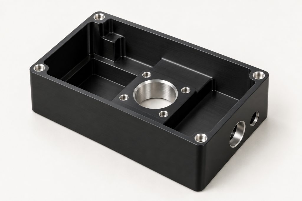
Housings and interface bodies
Housings and interface bodies combine internal pockets, connector openings and cover interfaces. We supply machined bodies with the specified appearance finish and masking for functional bores, threads or electrical contact areas.
CNC milling produces pockets, mounting faces and hole patterns in plates, supports and housings. Turning suits shafts, spacers, sleeves and knobs. Features on several sides are reviewed for datum continuity, workholding and tool access before the route is confirmed.
Instrument Housing Project
We machined 12 prototype instrument housings in 6061-T6 aluminium for a measurement-device development project. Each housing was specified at 120 × 80 × 35 mm; specialist finishing and final checks followed machining.
| Feature | Drawing requirement | Manufacturing and inspection |
|---|---|---|
| Locating bore | Ø20.000–20.020 mm on the selected bore | Masked during anodising; final fit confirmed after finishing. |
| Mounting face | Flatness 0.03 mm over 100 × 70 mm | The defined functional face is the inspection extent, with support and measurement conditions tied to the requirement. |
| Finish and contact regions | Black anodised appearance to the specified sample | Selected locating and contact regions were masked; CMM inspection covered the agreed features. |
The 12 prototypes completed the agreed dimensional and fit checks. Machining took eight working days, with three further working days for outsourced finishing and final checks: eleven manufacturing working days to dispatch. A later 200-part batch was planned; the controlled drawing was prepared for that next stage.
Locating Features and Assembly Fit
An individual part’s dimensions and the assembled instrument’s positioning check answer different questions. For removable holders and fixtures, the drawing should identify the locating features and the agreed assembly check.
| Interface | Function | Drawing and acceptance details |
|---|---|---|
| Locating bores, pins and datums | Establish the component’s position | Mating geometry, fits and the relationship between locating features. |
| Mounting and contact faces | Seat the component against its support | Functional face, loading, flatness or position requirement and measurement condition. |
| Fasteners and clamping features | Hold the component against its locators | Hole or thread pattern, clearance and assembly access; the actual locating role depends on the design. |
For laboratory automation components supplied as a set, the quotation can include matched part numbers and revisions, specified hardware, inserts and simple mechanical assembly.
Materials and Finishes for Instrument Parts
| Material family and grades | When it fits | Conditions to specify |
|---|---|---|
| Aluminium: 6061-T6 or 6082-T6 | Low-mass housings, plates and structural brackets. | Geometry must meet load and stiffness needs. Specify material standard, condition and stock form; substitutions need agreement. |
| Stainless steel: 303, 304 or 316L | Metal interfaces where corrosion resistance drives selection. | Match grade to medium, temperature, finish and passivation. 303 cannot automatically replace 304 or 316L. Specify material documents. |
| POM: POM-C or POM-H | Guides, holders and locating contacts needing a polymer surface with sliding and wear resistance. | Stock grade, load, temperature, chemical exposure and dimensional measurement condition; distinguish POM-C from POM-H. |
Surface treatment can change a functional dimension, so agree the inspection stage. Identify masked bores, threads and contact areas on the drawing. The quotation defines the finish, masking and final inspection scope; specialist anodising and passivation are coordinated through selected partners.
From Prototype to Repeat Orders
Prototype and review
We manufacture parts for interface and assembly trials, resolving material, tool-access, finish and inspection questions from your model or drawing before production.
Approve the revision
The approved part number, revision, material, finish and critical features define the next order. Model and drawing must agree before manufacture.
Release the next quantity
We quote repeat quantities and alternative batch sizes against the current revision. Changed features, materials or finishes may change the machining and inspection requirements. Estimated annual demand is separate from the ordered quantity; manufacturing lead time and shipping are confirmed separately.
Dimensional Inspection and Order Documents
Our in-house dimensional inspection supports precision machining for scientific instruments. CMM, optical measurement and suitable gauges check the agreed features under the specified measurement conditions.
Key-feature dimensions
Dimensional reports cover the locating dimensions, mounting faces, threads or other quoted features. Full-dimensional or individual-part reporting is agreed separately.
First-article records
Formal customer FAI is agreed separately from routine first-piece checks: ballooned drawing, feature numbers, results, methods and acceptance criteria.
Material and process records
Quoted material-source records, conformity statements and specialist-process documents can accompany the order, linked to the applicable part number, revision and material batch.
Discuss Your Instrument Parts
Enough to start
Send a drawing, model or useful part/use description, plus quantity or programme stage when known. We can discuss the remaining details.
Helpful for quotation
Where available, add the drawing revision, material, critical dimensions and tolerances, finish, use conditions, document needs and delivery country. We return a quotation identifying the proposed manufacturing route and agreed inspection deliverables.
Upload PDF drawings or ZIP files containing STEP or IGES models: up to three files, 10 MB per file. Keep the part identities and revisions matched within the package.