Precision CNC Machining for Parts That Need to Fit
Great Machining manufactures housings, brackets, shafts, sleeves and fixtures with controlled mating and locating features. From functional prototypes to repeat orders, we machine your specified material and inspect the dimensions that matter to the assembly.
Selected metal features can reach ±0.01 mm after review of the material, geometry, datums and inspection requirements, normally for features no larger than 100 mm.
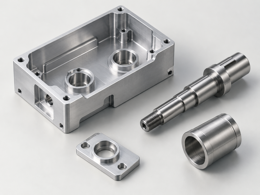
Illustrative part geometry.
Machining Routes for Your Critical Features
The shape of the part and the relationship between its features determine the machining route. Our in-house milling, turning, wire EDM and grinding capabilities support different parts of that job.
We mill housings, brackets, locating plates and fixtures with pockets, mounting faces, holes and datum surfaces. Three-axis or five-axis machining follows tool access and feature direction; fixturing and the roughing-to-finishing sequence preserve relationships between faces. Deep pockets, thin walls and probe access need assessment. More axes alone do not guarantee tighter tolerances.
We turn shafts, sleeves, rings and fittings, adding side holes, slots or flats through mill-turn machining. Slender sections need suitable support. Length-to-diameter relationships and measuring access influence the route; diameter, roundness, surface finish and specified runout remain separate requirements.
Wire EDM produces suitable profiles, fine slots and tooling features in conductive materials where cutter access is difficult. Section thickness, wire access and surface requirements determine suitability; it cannot replace machining for every blind pocket or surface.
Separate grinding or finishing can bring selected bores, shaft sections and planes to the required fit. Machining allowance, workholding and acceptance method are assessed together. Tolerances down to ±0.005 mm apply only to separately assessed ground or finished fitting features, not general CNC machining or every dimension.
Put Precision Where the Part Needs It
Concentrating tighter control on the functional features keeps the part suited to its assembly without tightening every dimension.
| Functional feature | Machining and control | Inspection and final condition |
|---|---|---|
| Mating or locating bore | Mill, bore or turn the fit; assess secondary finishing if needed. | Suitable bore or coordinate measurement; separate size, form and datums. Agree masking or post-treatment acceptance. |
| Shaft or sleeve fit | Turn or mill-turn; support slender sections and finish selected surfaces. | Check diameter, length and surface requirements separately from roundness or runout, after the agreed final operation. |
| Locating hole pattern | Machine the holes relative to drawing datums with a suitable setup sequence. | Coordinate checks establish datum-related location; diameter alone does not. Retain the controlled drawing revision and final-treatment condition. |
| Mating plane | Rough and finish with suitable support; assess grinding if needed. | Specify flatness area, support and measurement state; flatness differs from ± size tolerance. Agree post-finish acceptance. |
Selected metal dimensions: ±0.01 mm after review, normally for features up to 100 mm, with suitable material, geometry, datums and inspection.
Special fitting features: ±0.005 mm may be possible on separately assessed ground or finished bores, shafts or planes.
Flatness example: 0.03 mm over a selected 100 × 100 mm functional face, with the support and measurement state agreed. Larger faces need a separate assessment.
Drawing requirements govern. Agree general tolerances before ordering; an ISO 2768 class follows nominal size ranges, not one tolerance for every dimension.
Precision Aluminium Parts for Equipment Builds
Aluminium housings, mounting brackets and fixture plates combine machined interfaces with the surrounding structure. We machine pockets, locating bores, mounting patterns and contact faces to suit equipment assembly, then coordinate the required finishing operations.
6061-T6 and 6082-T6
Plate or bar for specified housings, brackets and fixtures. Match the drawing standard, temper and stock form; these alloys are not automatic substitutes.
7075-T6
For specified higher-strength structural components. Load requirements, heat-treatment condition and finish determine suitability.
For anodized housings, we separate machining and finishing stages and define masked locating or contact areas to preserve the specified assembly fit.
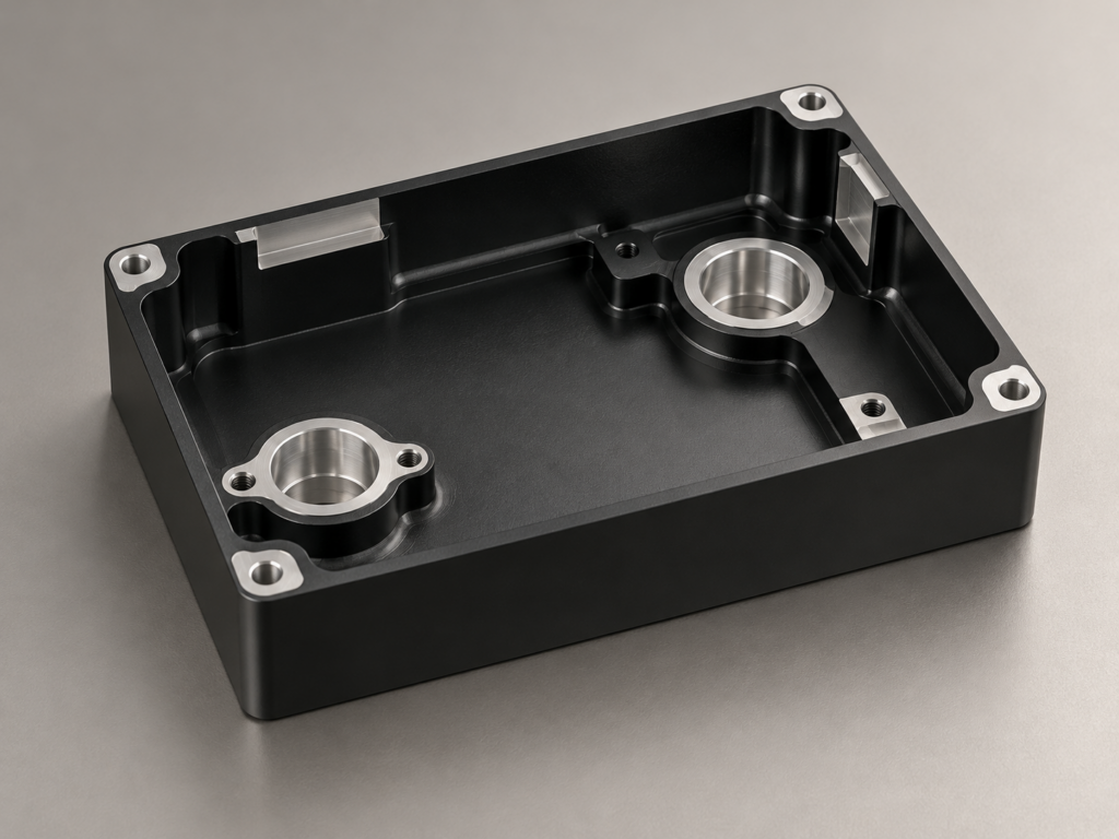
Illustrative aluminium housing geometry.
Materials Matched to the Feature
Material choice affects tool access, burrs, dimensional stability and the finishing sequence. We quote the specified grade and condition for the part; a material family name does not establish an equivalent grade, available stock or a certificate requirement.
Selected precision plastic features can reach ±0.05 mm after review of a stable material and small, supported geometry. Moisture, residual stress, temperature and the agreed measurement state matter; metal-part tolerances are not transferred automatically to plastics. Share the intended operating conditions when they affect the fit.
Keep the Fit Through Finishing
We supply deburred machined parts and coordinate specialist finishing with selected partners. Mark the mating, locating, sealing and electrical-contact areas so the finish supports the part’s function.
As Machined and Deburred
Retain machining marks where acceptable, with edge breaks and specified functional surfaces defined on the drawing. Accessible finished faces can be assessed for Ra 0.8–1.6 μm according to the material, shape, tooling and machining direction.
Bead Blasting and Anodizing
Define the texture and appearance sample for suitable substrates. For normal or hard anodizing on appropriate aluminium alloys, specify the coating and identify holes, threads and contact areas that need masking or final-size verification.
Passivation and Plated Finishes
Passivation is available for applicable stainless parts. Electroless nickel and specified electroplating, including zinc on suitable substrates, require an agreed system, coverage and final-size condition. The plating route follows the actual base material.
Polishing, Black Oxide and Heat Treatment
Define allowable edge changes for polishing and the protection requirements for black oxide on appropriate steel. For heat-treated parts, hardness, distortion allowance and the sequence of final machining or grinding belong in the manufacturing plan.
Precision in Two Manufactured Part Projects
6061-T6 Instrument Housing
A 12-piece prototype project used 120 × 80 × 35 mm aluminium housings for industrial measuring equipment. The drawing called for a selected locating bore of Ø20.000–20.020 mm and flatness of 0.03 mm over a 100 × 70 mm mounting face, alongside a specified black anodized appearance.
We separated roughing and finishing, masked the locating bore and designated contact areas, and checked the agreed features by CMM. Final checks addressed the specified dimensions and fit after the finishing sequence. The approved drawing also defined a planned later 200-piece batch; that plan is distinct from a completed repeat order.
316L Precision Sleeve
A 100-piece project supplied 316L sleeves, 45 mm long, with an 18 mm outside diameter and a 10 mm bore. Drawing requirements included an outside diameter of 18.000 ±0.010 mm, a bore of 10.000–10.020 mm and Ra ≤0.8 μm on selected fitting surfaces.
The route combined turning, finishing of the fitting surfaces and controlled deburring. We rechecked the agreed features after passivation, with fitting diameters, length and surface requirements recorded separately.
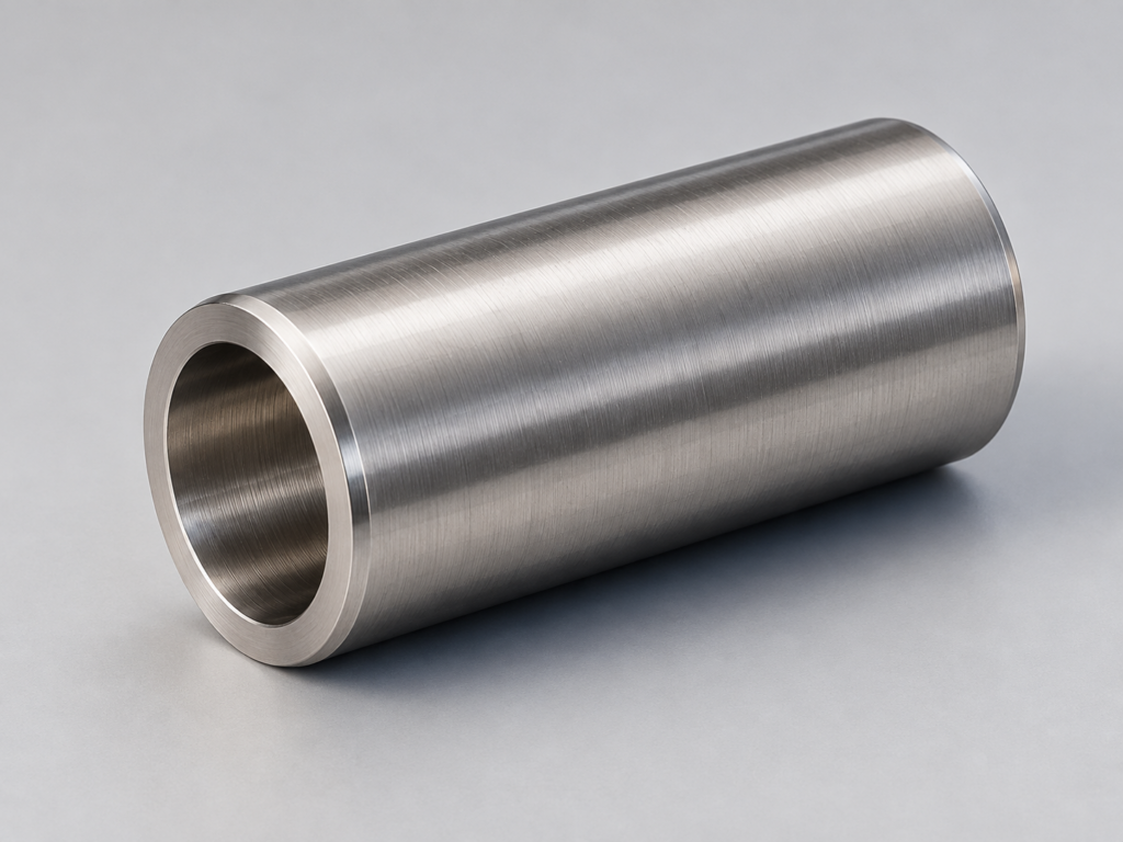
Illustrative sleeve geometry.
Inspection Around the Features That Matter
We inspect the agreed characteristics so the delivered parts can be checked against the controlled drawing and order. The measuring method follows the feature, access and acceptance requirement.
Datums, coordinates and geometry: our in-house CMM supports suitable accessible features within its measuring range. Probe selection, workholding, environment and measurement uncertainty must fit the requirement. Having a CMM does not by itself establish reliable acceptance of every ±0.005 mm feature.
Profiles, fits and surfaces: two vision measuring instruments support appropriate small profiles and features. Micrometers, pin gauges, thread gauges and other task-specific instruments address suitable sizes and threads; a surface roughness tester checks accessible specified faces under suitable measurement conditions.
Checks begin with the drawing revision, material and critical features. Incoming material checks, first-piece and in-process inspection, return checks after outside treatment, and final verification follow the agreed plan. Repeat orders retain the relevant version and manufacturing records, with changes identified before production.
Key-dimension reports can be included in the quotation. A formal first-article package can include a ballooned drawing, feature numbers, nominal values, tolerances, results and methods when agreed. Routine first-piece checks and a formal FAI package are different deliverables; 100% full-dimensional inspection and individual-part reports are quoted separately.
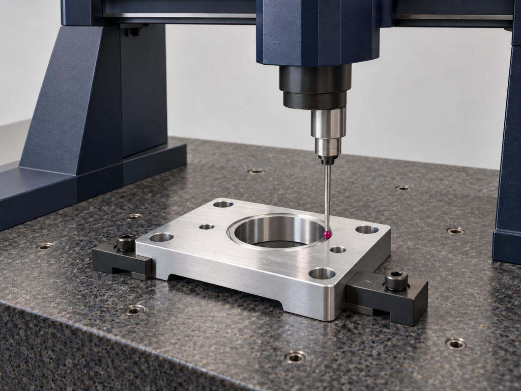
Illustrative measurement setup.
A Practical Route to Parts That Fit
Source complementary equipment parts through one project contact—from milled housings and brackets to turned shafts, sleeves and engineering plastic components. Great Machining combines in-house CNC machining and dimensional inspection with selected partners for specialist finishing.
Our team coordinates the drawings, production stages and agreed delivery scope for the order. Manufacturing-location or subcontracting restrictions are agreed at quotation, so the proposed supply arrangement fits your purchasing requirements.
Precision Machining Questions
Send Your Part for a Precision Machining Quote
Start with a drawing, CAD file, sample or useful description, plus quantity or project stage when known.
Helpful for quotation, when available: critical dimensions, tolerances, surface finish, material, intended use or operating conditions, and any inspection or delivery requirements. Our team can clarify missing details, recommend a manufacturing route and quote the finished components. You can inquire before every detail is settled.