Custom Metal Brackets
CNC machined mounting brackets for sensors, cameras, actuators and equipment interfaces—made from your CAD files and drawings.
Great Machining supplies prototypes and repeat batches with specified materials, mounting features and dimensional inspection. Send a drawing or describe the mounting problem to start a quotation.
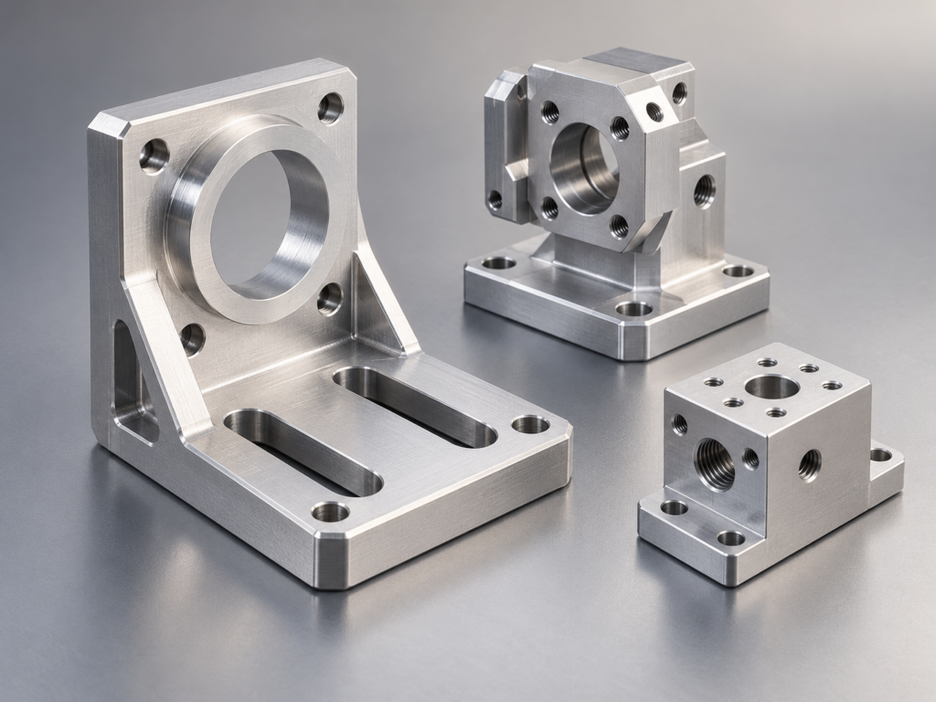
AI-generated bracket illustrations show example geometries, rather than photographed customer parts.
Find the Mounting Bracket for Your Assembly
Custom mounting brackets connect the component to its supporting structure. The useful starting point is the interface: what attaches, where it locates and which direction needs adjustment.
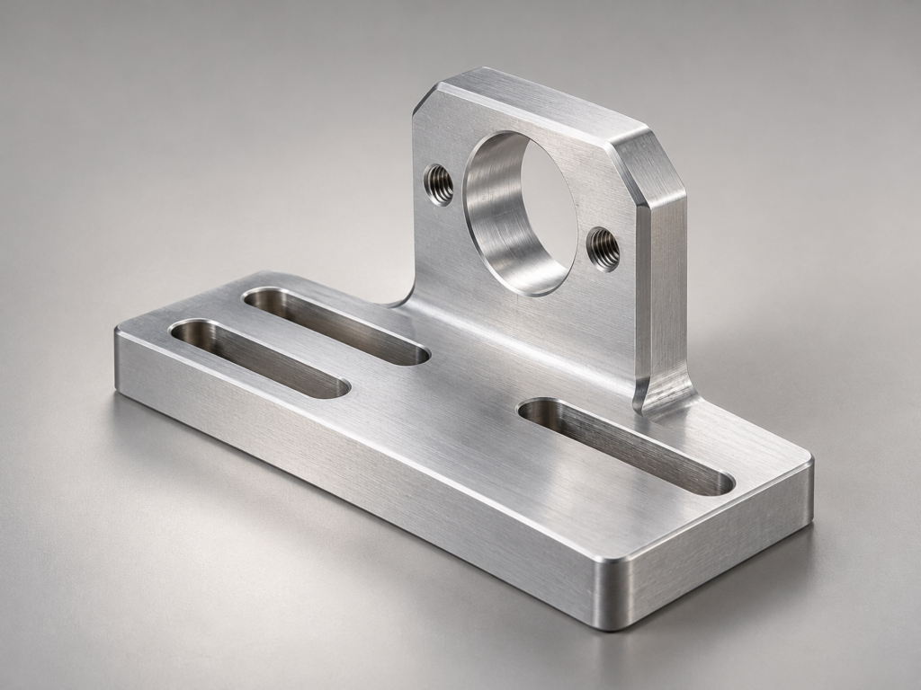
Sensor Mounting Brackets
Machined blocks and slotted mounts for positioning a sensor relative to a target or fixture. Specify the sensor interface, adjustment direction and fastening arrangement. Where location must be repeatable, identify the locating features separately from the clearance holes and adjustment slots.
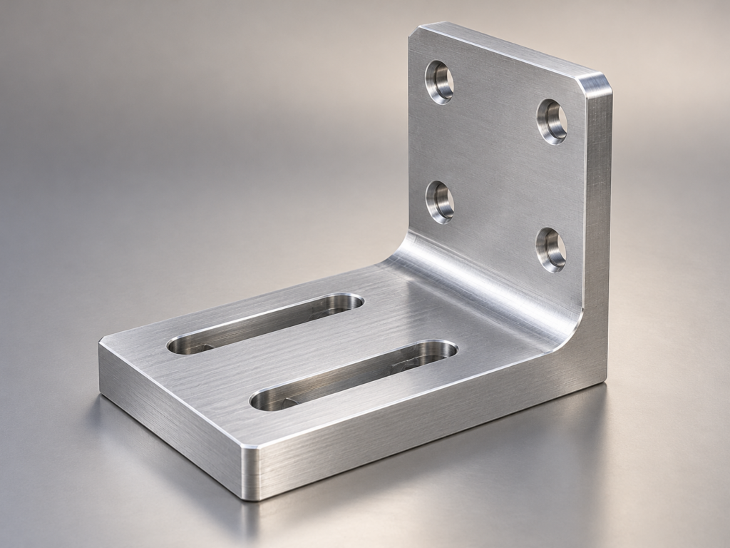
Camera Mounting Brackets
Right-angle mounts, adapter plates and offset supports for equipment cameras. Mating-face orientation, hole pattern and access for screws determine the geometry. Include any required adjustment range and the space needed around the camera, lens and connectors in the assembly information.
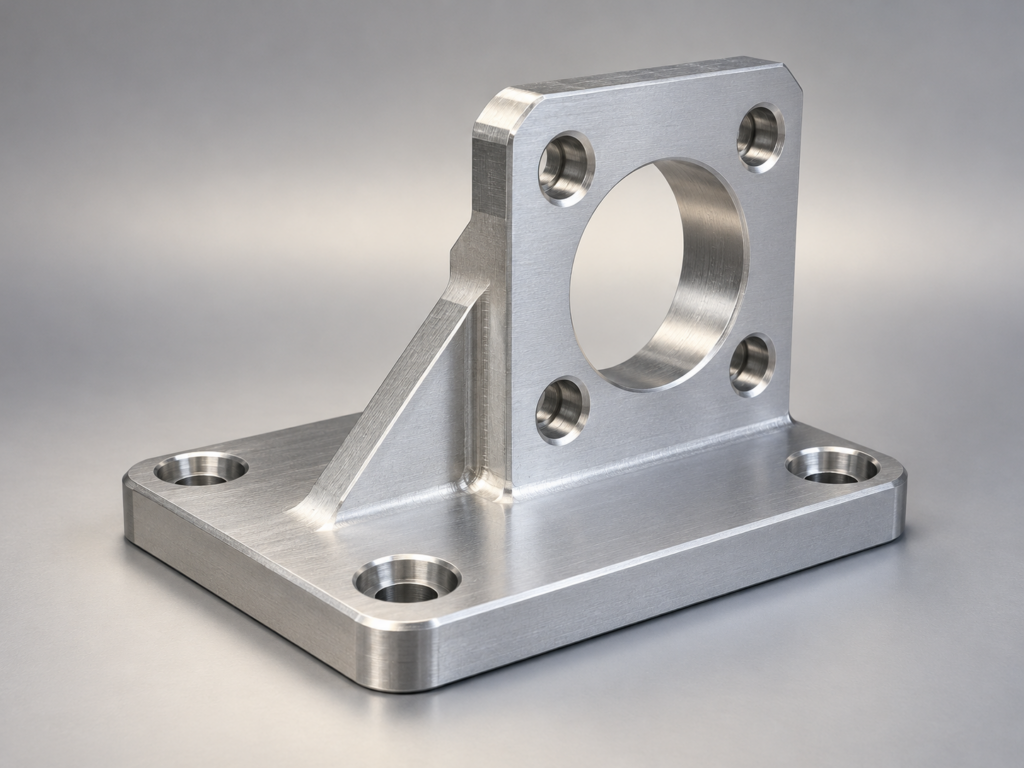
Actuator Interface Brackets
Mounting feet and multi-face supports connecting an actuator or end-effector interface to the machine. The drawing defines bores, fastener patterns and reference faces. Load direction, unsupported length and allowable movement help define the design requirements; the machined part is supplied to the agreed design.
Project: A Multi-Face Robot Bracket
A robotic end-effector development project called for 20 prototypes in 7075-T6 aluminium. Each bracket measured 160 × 100 × 65 mm and carried mounting features in several directions.
Selected hole diameters required ±0.02 mm. Hole position was specified separately at Ø0.05 mm relative to defined A/B/C datums. A five-axis route addressed the multiple feature directions, using a customer-approved model with changes to non-critical regions.
The brackets were delivered as machined in 10 working days, with the agreed dimensional records. These values describe this project’s material, geometry and inspection requirements; the quotation defines the scope and schedule for a different bracket. Structural strength, fatigue and machine-level performance require separate validation.
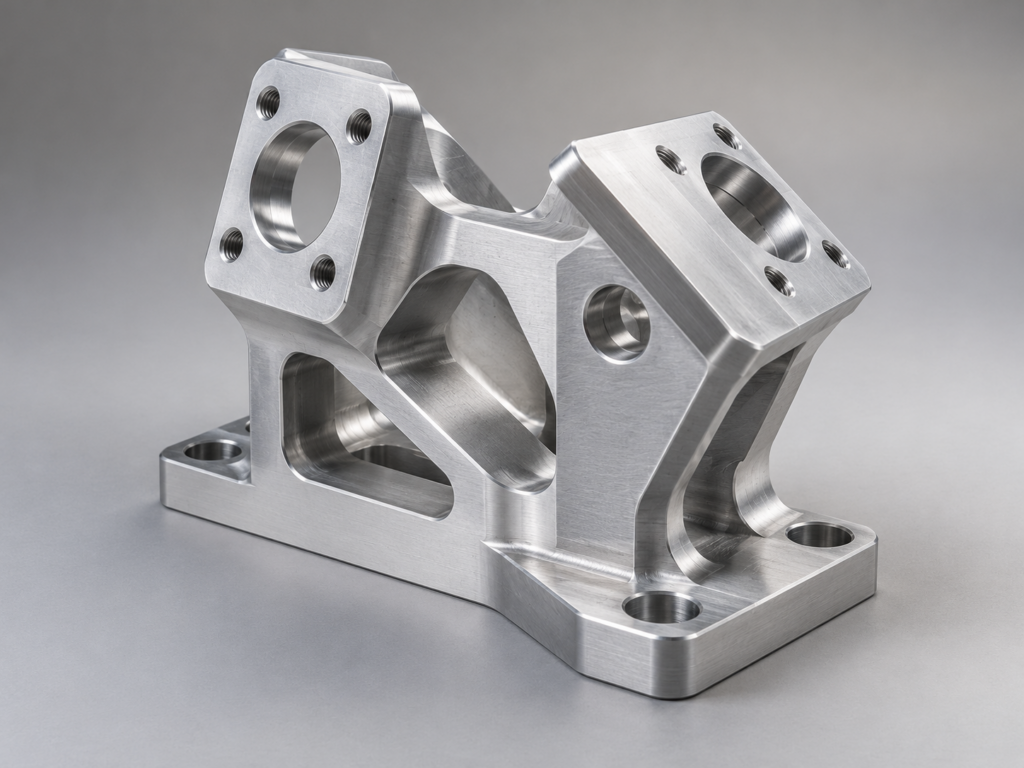
AI illustration of multi-face bracket geometry; not a photograph of the project part.
Stock, Formed or CNC Machined?
The manufacturing route should follow the interfaces and quantity. A custom bracket does not always need machining from solid stock.
A Matching Catalogue Part
A standard bracket is worth considering when its hole pattern, envelope, material and adjustment range already meet the assembly requirements. This page covers drawing-based manufacture; it is not a stocked hardware catalogue.
A Cut and Formed Bracket
Simple L, U or offset shapes in sheet material may suit cutting and bending. Sheet thickness, bend direction, internal radius and hole positions relative to bends belong in the specification. Great Machining supports this route through selected manufacturing partners.
A Machined Bracket
CNC machining suits thick sections, pockets, machined locating faces, threaded features and mounting details in several directions. Geometry, tool access and inspection requirements determine whether we use three-axis or five-axis machining.
Define What Adjusts and What Locates
A useful bracket drawing separates assembly clearance from the features that control position. It also identifies the relationships between mounting faces, rather than applying the tightest tolerance everywhere.
Holes, Slots and Fastener Access
Show the slot direction, usable adjustment range, fastener size and any counterbore or countersink. Mark locating bores or dowel holes separately. A hole-size tolerance and a position tolerance answer different questions: whether the mating feature fits, and where its axis lies relative to the drawing datums.
Angles and Contact Faces
Identify the faces that contact the equipment and the reference used for the mounting angle. State flatness, perpendicularity or angular requirements on the relevant features when needed. Keep screw-head, tool and connector clearance in the assembly model so the bracket can be installed in its intended position.
Section Geometry and Stiffness
Stiffness depends on the bracket geometry and how it is supported and loaded. If movement matters, include the load direction, support spacing and allowable displacement in the requirements. Material grade alone does not establish bracket stiffness or a safe load rating. Relief pockets, thin sections and internal radii are reviewed for machining access and support.
Materials and Finishes for the Mounting Interface
Material choice includes the grade, temper and stock form. Finish requirements then need to preserve the holes and contact faces that matter to the assembly.
Aluminium Brackets
6061-T6 and 6082-T6 plate or bar are options for machined aluminium brackets; the specified standard and temper remain part of the order. They are not automatic substitutes. 7075-T6 is available for designs that specify it, including the multi-face project above. See Aluminium CNC machining for the material route.
Steel and Stainless Steel
Steel mounting parts are quoted to the specified grade and hardness condition, with heat treatment and surface protection identified where needed. Stainless options include 303, 304 and 316L, selected for the drawing and environment. These grades are not interchangeable; welding, corrosion requirements and finishing affect the choice.
Formed Sheet Alternatives
For a partner-produced sheet bracket, 5052-H32 aluminium is a separate material and process choice from a 6061-T6 or 6082-T6 machined component. Confirm thickness, bend geometry and final coating with the proposed route. A similar outline does not make the two constructions equivalent.
Finish Around the Functional Surfaces
As-machined, deburred parts retain machining marks. Specialist anodising, plating, passivation and other compatible finishes are arranged with production partners. Identify critical holes, threads, contact faces and any electrical grounding areas that need masking. Agree whether dimensional acceptance applies before or after finishing; coating thickness is not a universal conversion to the dimensional change of every feature.
Inspection Tied to the Bracket Drawing
Our in-house dimensional inspection follows the agreed features and inspection plan. First-piece, in-process and final checks connect the drawing revision to the supplied parts.
Locating Features and Datums
The plan distinguishes hole diameter from datum-based position and relates each requirement to a suitable method. CMM measurement can support coordinate dimensions and GD&T within its applicable range; probe access, setup and measurement conditions must suit the feature.
Faces, Threads and Final Condition
Mounting-face geometry, thread requirements and relevant finished dimensions are checked as ordered. Specify the thread standard, tolerance class and effective depth. Appearance areas and deburring requirements are agreed alongside the dimensional requirements, especially where a bracket sits near cables or mating surfaces.
Reports and Part Identity
Critical-dimension reports can be included in the quotation. Full-dimension, per-part inspection and formal first-article documentation are separate scopes. Labels and packing records identify the part number, revision, quantity and applicable batch. Explore Quality control and inspection for methods and document options.
From Prototype to Repeat Brackets
Build the First Version
We clarify the material, critical interfaces and manufacturing route before confirming the quotation. Production follows the approved revision and agreed inspection requirements; specialist finishing is included where specified.
Repeat the Approved Revision
For subsequent batches, confirm the drawing revision and any changes to material, finish or documentation. Revised hole patterns and mounting angles need to be carried through the manufacturing and inspection requirements. Parts are packed and labelled to keep the ordered versions identifiable.
Simple aluminium CNC prototypes typically take 5–7 working days for 1–10 parts in normally stocked material, with conventional tolerances and deburring. Complex or multi-face prototypes typically take 8–12 working days for 5–20 parts; special-material procurement and heat treatment are scheduled separately. Manufacturing time follows the confirmed production calendar and starts once files, technical requirements, order conditions, any required payment and material availability are confirmed. Specialist finishes, customer approvals, drawing changes, international transport and customs add time. Your quotation confirms the schedule for the actual order.
Bracket Ordering Questions
Send Us Your Bracket Requirement
Start with the part file or a useful description, intended use and quantity. Grade and temper, critical holes and datums, finish, required reports and delivery country help refine the quotation. Great Machining will confirm the manufacturing route and agreed deliverables for your design.
For confidential designs, enquire without attachments first so we can agree an NDA and file-transfer arrangements. The current quote form accepts non-confidential files.