Custom Machined Enclosures & Housings
Machined housings, pocketed bodies, covers and interface panels for instruments and electronic equipment. Great Machining makes custom metal and engineering plastic components from your drawings, supporting prototypes, small batches and repeat orders.
Get the cavities, mounting features and finished interfaces your assembly needs, with material, appearance and dimensional records agreed for the order. Our in-house team handles CNC machining and dimensional inspection; specialist finishes are arranged through selected production partners.
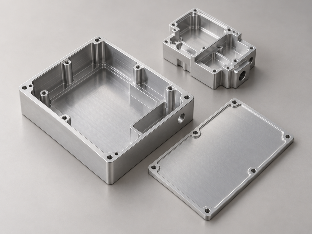
AI illustrations show representative component geometry. They are not photographs of delivered parts or dimensional drawings.
Find a form close to your enclosure
A small enclosure may combine a machined body, a separate cover and local mounting features. We quote the individual components or an agreed mechanical parts package from your design.
Instrument housings
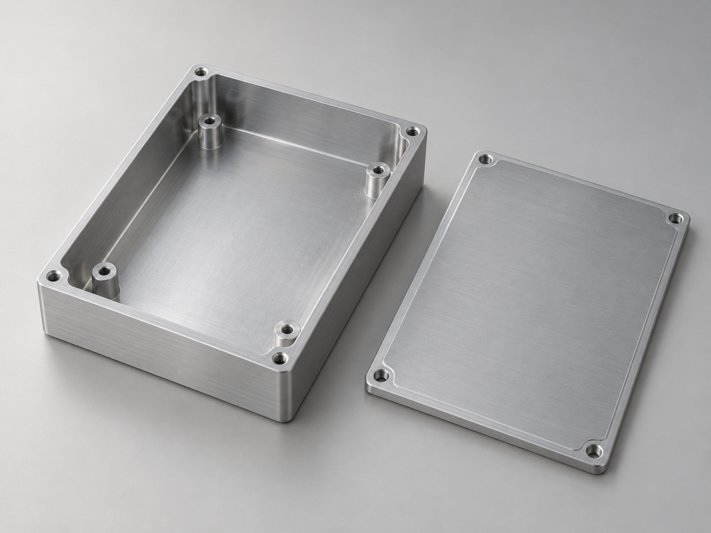
Open bodies bring internal mounting bosses, locating holes and a cover interface into one component. Component clearance and mounting references guide the cavity layout.
AI illustration — an open instrument housing with mounting bosses and a separate cover.
Pocketed and stepped bodies
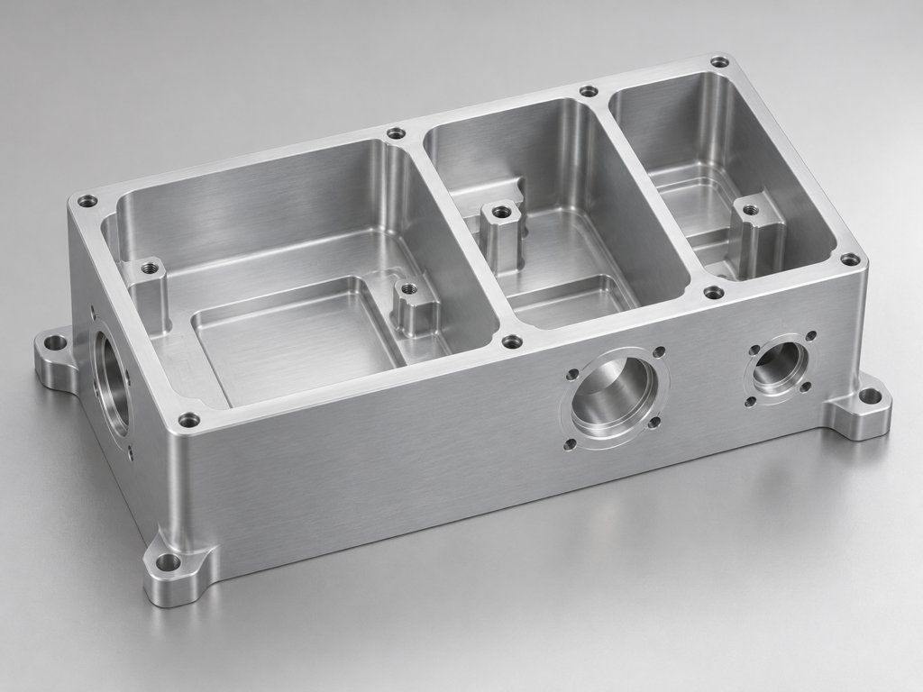
Multiple cavities, raised pads and side openings can be combined in one machined body. Tool access and wall support matter where a narrow pocket sits beside a deep cavity or a thin wall.
AI illustration — a multi-pocket housing with stepped floors and side openings.
Covers and interface panels
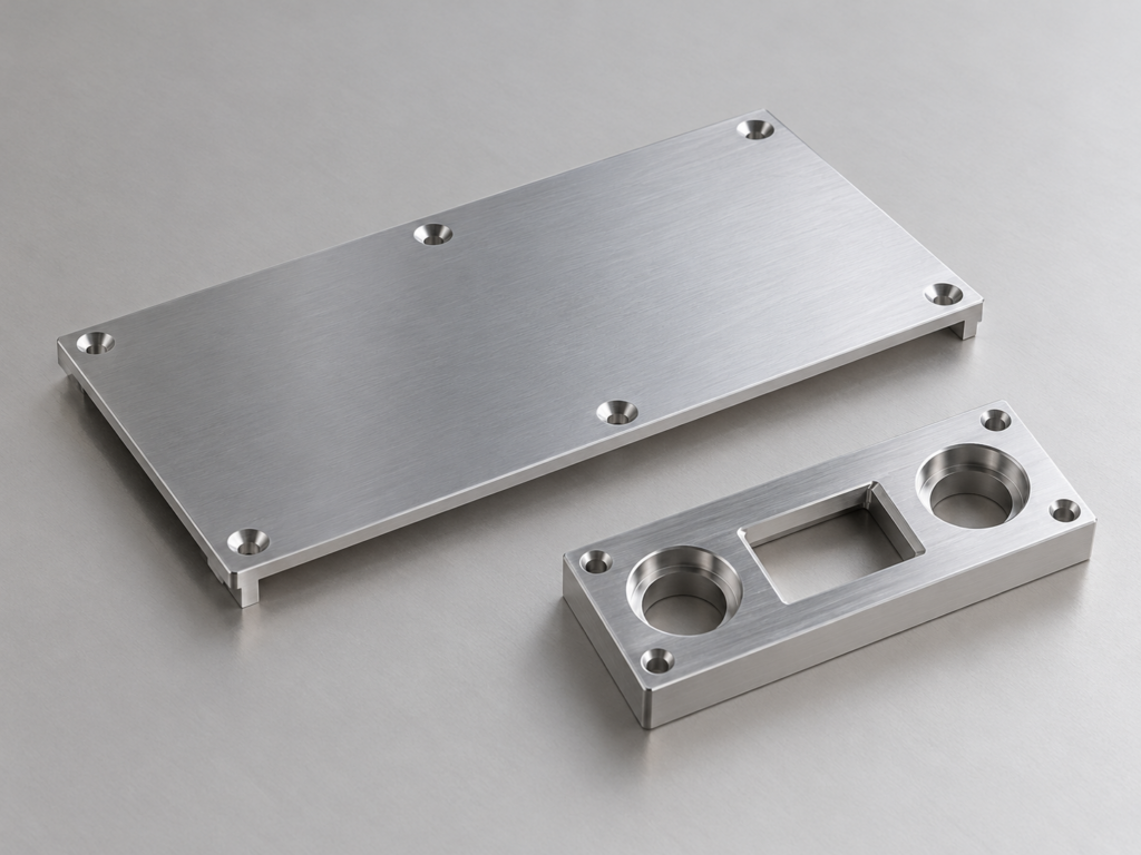
Covers close the body; thicker interface panels carry connector openings, counterbores, threads and locating features. The seating face, openings and visible surfaces can be specified together.
AI illustration — a cover plate and a separate connector interface panel.
Project example: 6061-T6 instrument housings
We made 12 prototype housings for an industrial measurement-equipment development team. Each 6061-T6 housing measured 120 × 80 × 35 mm. The drawing specified a locating bore of Ø20.000–20.020 mm and flatness of 0.03 mm across a 100 × 70 mm mounting plane.
Roughing and finishing were separated. The locating bore and specified contact regions were masked for black anodizing, with appearance referenced to an agreed sample. Fit was confirmed after treatment, and the agreed features were checked by CMM. The 12 samples completed the specified dimensional and fit checks.
For this project, machining took eight working days, followed by three working days for outsourced finishing and final inspection: 11 working days to dispatch. The next planned stage was a 200-piece batch.
Make the internal features work together
Cavity geometry and assembly interfaces need to be considered together. A change that improves tool access must still preserve component clearance, seating and the controlled drawing requirements.
Cavity depth, corners and walls
Deep cavities and small internal radii can require longer or smaller tools, reducing stiffness and making machining more demanding. Thin walls also need suitable support. Where the design permits, a larger corner radius, a wider opening or a separate cover can improve access. We discuss changes with your team before altering the approved geometry.
Datums, mounting features and cover seats
Use the assembly references to define the relationship between locating holes, mounting pads, connector openings and the cover seat. Tight control on a functional interface is useful; applying the same tight tolerance to every exterior dimension adds machining and inspection work without necessarily improving the fit.
Seal grooves and mating faces
We machine specified grooves and mating faces to the drawing. Groove dimensions, surface requirements and the finished measurement state need to be defined with the mating components. An IP rating or leak-tight assembly requires appropriate gasket selection, assembly conditions and testing; machined geometry alone does not establish that result.
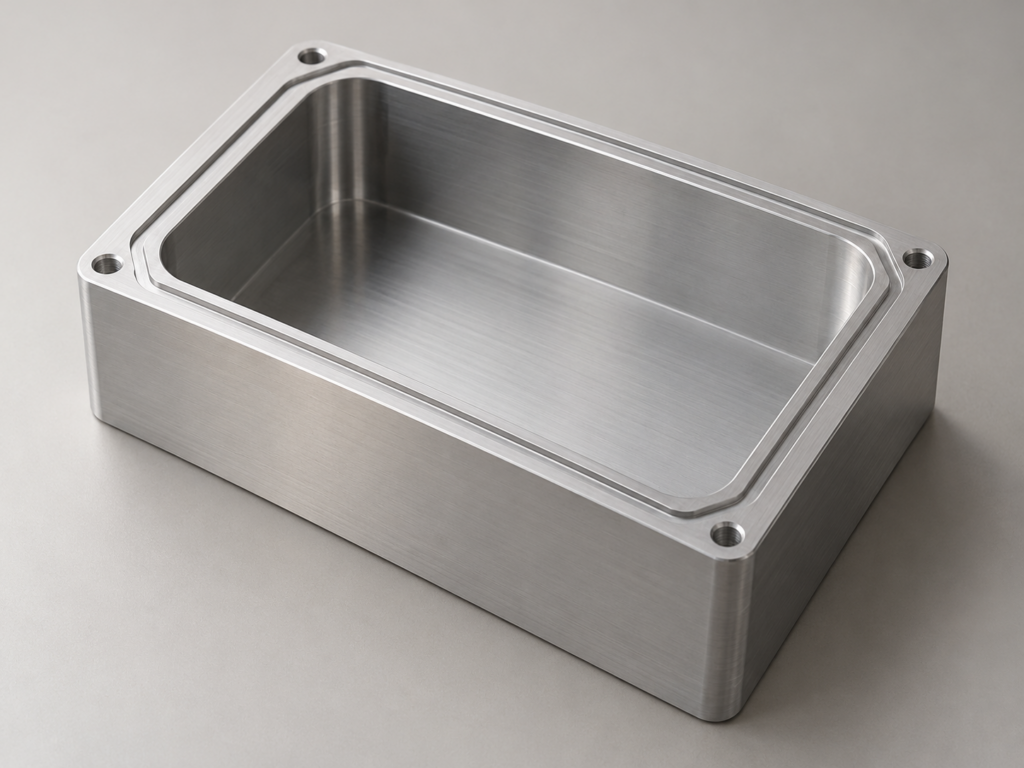
AI illustration — a housing rim with a continuous groove and perimeter screw holes; it does not establish sealing performance.
Choose the manufacturing route for the geometry
Solid-stock machining is one option. The shape, quantity, tooling investment and critical features determine whether a formed blank is a better starting point. CNC machining and dimensional inspection are our in-house core; forming processes below are coordinated through selected partners.
Machining from solid stock
Useful for custom pockets, mounting pads and multi-face interfaces without a dedicated forming tool. Material removal, cavity access and the number of setups affect the work required. It suits development and repeat parts when these features justify machining.
Extrusion followed by machining
A continuous cross-section may suit an extruded body, with openings, threads and mating features machined afterwards. Confirm the alloy and temper, section, straightness, cut length, tooling and minimum procurement requirements before comparing costs.
Sheet metal fabrication
A formed shell or cover may suit larger, relatively open enclosures. Bends, joints, hardware and coatings need their own specification. It is a different construction from a billet body with local deep pockets and integral mounting pads.
Casting followed by machining
A repeated near-net shape may justify a casting tool, followed by machining of selected interfaces. Alloy, tooling, casting quality, machining allowance and final inspection must be considered together. Quantity alone does not establish the best route.
For plastic designs, a printed model can help evaluate geometry, while repeat production may justify injection tooling. Printed, molded and machined stock materials are different product forms; a fit model does not establish the final material’s performance.
Specify the material and finish together
Aluminium housings
6061-T6 and 6082-T6 plate or bar are available for suitable CNC parts. Specify the required standard, temper and stock form rather than treating the two grades as automatic substitutes. For more material detail, see Aluminium CNC machining.
Stainless steel components
304 and 316L can be assessed for housing components where the specified environment and material requirements call for them. Confirm the actual grade, finish and any passivation requirements; one stainless grade should not silently replace another.
Engineering plastic components
Specified ABS or PC stock may suit a machined housing or cover; POM can be considered for appropriate internal locating and contact parts. Give the actual grade and operating requirements. Transparent PC stock does not by itself guarantee an optical-quality finished component.
Define visible surfaces using the required texture, color and an agreed reference where needed. Anodizing applies to suitable aluminium; bead blasting, painting and powder coating are assessed against the substrate and purpose. A cosmetic sample and a numerical roughness requirement answer different questions.
Mark the threads, locating features, contact areas and mating faces that need masking or controlled dimensions after treatment. The order must state whether final dimensions are accepted before or after finishing. Coating thickness is not a universal conversion for the size change of every feature.
Verify the features that control assembly
Selected metal dimensions, usually no larger than 100 mm, can be assessed for ±0.01 mm after review of the material, geometry, datums and measurement method. This is a feature-specific capability, not a promise for every dimension of an entire housing.
CMM checks can relate suitable features to the agreed datums; optical measurement, gauges and roughness measurement are used where appropriate to the geometry and access. The method must suit the feature and measurement conditions. Our Quality and dimensional inspection page explains the available methods and document options.
Agree the required dimensional report, material documents and special-process records with the quotation. Routine first-piece checks differ from a formal first-article report. Full-dimensional or individual-piece reports and 100% full-dimensional inspection are separate scopes.
From drawing to a planned delivery
We clarify the material, critical interfaces, finish and required records before quoting the manufacturing route and deliverables. Production follows the approved revision, with inspection and packaging matched to the order.
Material procurement, machining, specialist finishing and additional inspection can affect the schedule. The quotation confirms the manufacturing lead time and its starting conditions; transport and customs are separate from dispatch.
Enclosure enquiries
Send us your enclosure design
Send the available drawing, model or useful part description, with the intended use and quantity if known. If the material, finish or inspection needs are still open, tell us what the part must do.