CNC Machining for Robotics & Automation
Custom brackets, gripper fingers, locating blocks and mounting plates—made to your drawings for robot tooling, machine vision and automated fixtures.
Great Machining mills and turns metal and engineering plastic components for prototypes and repeat orders. In-house CNC machining and dimensional inspection give you parts made to the specified material, drawing revision and agreed inspection requirements.
A drawing, CAD model or useful part description and quantity are enough to start. For confidential designs, ask about an NDA and agree a transfer method before sending files.
Prototype & repeat supply · Milling, turning & five-axis · Drawing-defined inspection
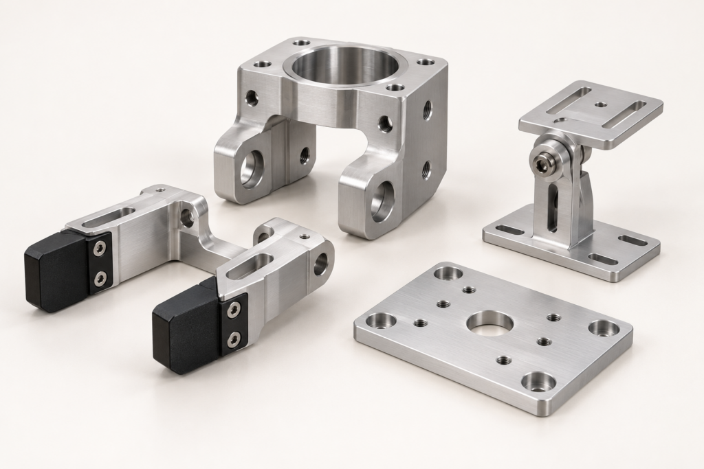
Illustrative component render. Geometry shown is not a customer drawing or a photograph of delivered parts.
Custom parts for robot tooling, vision stations & fixtures
From a camera mount to a robot-wrist interface, we manufacture the mechanical parts that connect, locate and support your equipment.
Custom parts are made to your design. Images are generic illustrations of these part types, not photographs of supplied components.
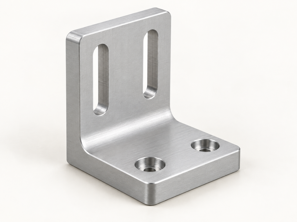
Sensor & camera brackets
Adjustable mounts for vision stations and sensors. Slots allow setup adjustment; locating holes and seating faces establish position. The device fixing pattern and datum relationships define which features need control.
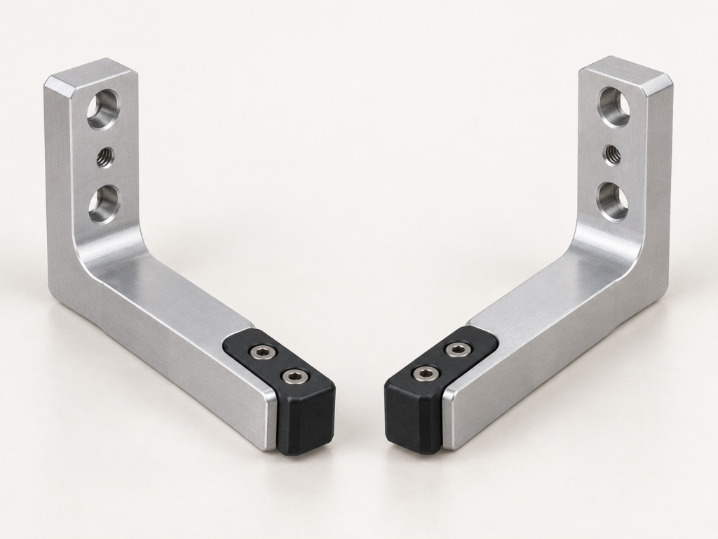
Gripper fingers & end-effector mounting parts
Custom fingers, tool plates and connecting brackets for robot tooling. Workpiece contact profile, wrist attachment, mass target and load direction guide the material and section geometry. Gripping force and structural performance require application validation.
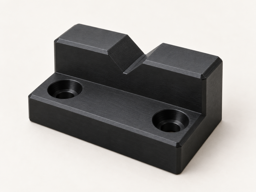
Locating blocks & contact parts
Blocks and pads for positioning workpieces in automated fixtures. POM is an option for selected contact and sliding parts; metal for rigid locating structures. Contact geometry, wear conditions and location relative to the mounting interface determine the requirements.
Automation mounting plates
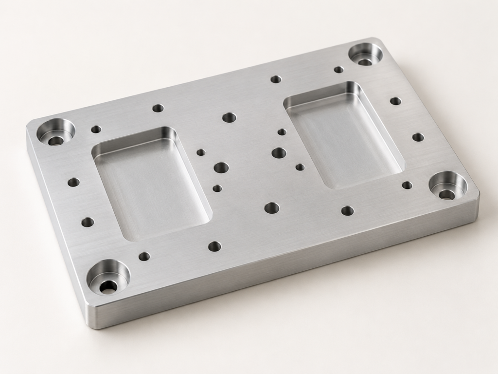
Plates for fixtures, sensor assemblies and equipment modules, with mounting patterns and datum faces made to your drawing. Define flatness in the required support or installed condition, and identify functional surfaces that need protection during finishing.
Define the fit, then choose the machining route
For robotics CNC machined parts, the important requirement is often how one feature relates to another. A bore size, hole position and seating-face condition describe different aspects of the fit; they should be called out separately where the assembly needs them.
Locate the component
Identify the datum faces, locating holes and mating bores. Put dimensional and geometric requirements on the drawing with a clear datum reference, rather than applying the tightest tolerance to every surface. Include the mating-part requirement when a clearance, transition or interference fit is intended.
Leave room for the process
Deep pockets, thin walls and long fingers affect tool access and clamping stability. Larger internal corner radii and relaxed nonfunctional tolerances can simplify machining and inspection. We review these features against your CAD and drawing before confirming the route.
Inspect the finished interface
Specify which dimensions apply after treatment, and identify masked bores, threads, datum faces or electrical contact areas. A coating can change a fit; the nominal coating thickness alone is not a reliable allowance for every feature.
Milling
For plates, slots, pockets, mounting patterns and prismatic brackets. Three-axis milling may suit accessible features; geometry and the required relationships determine the setup plan.
Five-axis machining
For angled features and access from several faces, including end-effector brackets. Five-axis machining can reduce separate orientations where the geometry allows; tool access and drawing requirements determine the setup plan.
Turning
For round locating pins, sleeves, spacers and related cylindrical components. Concentric features, bores and any subsequent milled flats or cross-holes are reviewed as one part route.
Core CNC machining and dimensional inspection are in-house. Specialist finishing and additional forming processes use selected partners where the project calls for them; the quotation identifies the agreed manufacturing route.
Prototype a robot-tooling bracket, then control the next revision
End-effector bracket: 20 prototypes in 7075-T6
A robot end-effector development project used a 160 × 100 × 65 mm bracket, machined from 7075-T6 aluminum by a five-axis route. The order covered 20 prototypes with a machined finish and agreed dimensional records, delivered in 10 working days for that project.
Selected bores were specified at ±0.02 mm, with hole position Ø0.05 mm relative to the stated A/B/C datums. These requirements and the 10-day schedule apply to this bracket project; other parts are assessed individually.
Two design revisions had calculated CAD part masses of 0.480 kg and 0.360 kg—a 25% reduction in calculated part mass. This comparison is not a weighing result or evidence of equivalent strength, stiffness, fatigue life or robot performance. Those remain design and application validation questions.
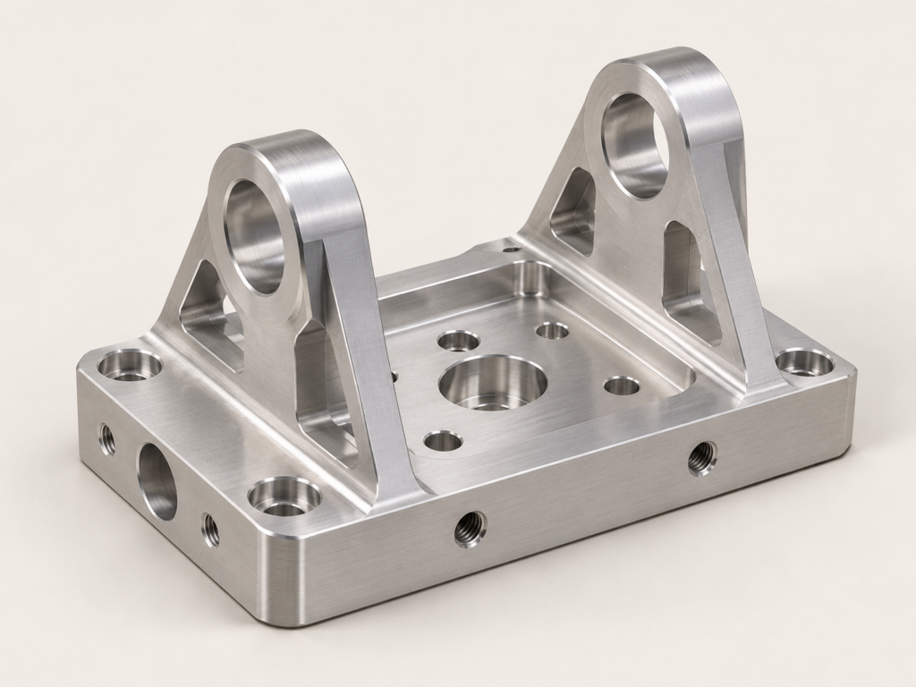
Illustrative bracket geometry only; this image does not reproduce the project’s CAD or document the delivered components.
First fit check
Start with the current part revision, prototype quantity and known interfaces. Agree the features to measure so the parts can support your assembly trial.
Revised build
Send the changed drawing and CAD together, with the revision and affected features identified. A change to a wall, hole pattern, material or finish may also change the machining and inspection plan.
Repeat supply
Reorder against the accepted part number and revision. Confirm quantity, material specification, finish and documentation again so the next batch has a clear acceptance basis.
Materials for brackets, contact parts & fixtures
Choose the grade for the part’s function and operating conditions. The material name, temper or polymer grade belongs on the drawing or enquiry; similar names are not permission to substitute.
6061-T6 / 6082-T6 aluminum
Options for mounting plates, sensor brackets and tooling structures. Specify the required alloy and temper: 6061-T6 and 6082-T6 are separate procurement grades. For anodized parts, define the fit after treatment.
7075-T6 aluminum
For designs that call for this higher-strength alloy, including the bracket example above. Stiffness and fatigue performance also depend on geometry and loading; select the section and surface treatment for the application.
Stainless steel: 303 / 304 / 316L
For mounting, locating and contact components where stainless steel is specified. Select the grade for the environment and machining requirements, with passivation and material documents defined for that grade.
Steel: 1018 / 1045 / 4140
For locating, supporting and fixture components. Specify grade, material condition and any hardness or heat-treatment requirement. Heat treatment and protective finishing affect the process sequence and final dimensional acceptance.
POM-C / POM-H
For selected guides, pads and locating or sliding contact parts. Specify POM-C or POM-H and the measurement conditions. ESD, food-contact or other special requirements need an appropriate specified grade and supporting documents.
Finish the surface without losing the interface
Appearance is one part of the decision. For automation machined parts, friction, corrosion exposure, contact surfaces and the final fit can change which treatment is appropriate. Finishing scope and acceptance are confirmed with the quotation.
Agree what will be checked and supplied
Dimensional inspection can establish whether the measured component features meet their drawing requirements. It does not validate an assembled robot’s accuracy, gripping force or operating safety.
We can agree key-dimension reports, material documents and a Certificate of Conformity with the order. First Article Inspection, full-dimensional inspection and measurement of every part are separate scopes to define before production. CMM, optical and conventional measurement methods are selected for the feature and agreed requirement.
Structural, cycle-life and assembly testing are separate from dimensional inspection. If required, define the samples, test conditions, responsibilities and deliverables with the order.
Robotics & automation machining FAQs
Send your next component for a quote
For custom machined components for automation equipment, start with a drawing, CAD model or part description and estimated quantity. Include the current revision if known; early enquiries are welcome before every detail is settled.
For a more precise quote, add the assembly location, material, critical fits, finish, inspection records and delivery destination. Include relevant load, wear or environmental conditions. STEP or IGES geometry with a dimensioned PDF communicates shape and acceptance requirements together.
Your quotation sets out the material, manufacturing route, quantity, finish, inspection records and lead time, with packing and freight scope identified.