Prototype CNC Machining
Get metal and engineering-plastic prototypes machined from specified stock for assembly checks, functional tests and design iterations. Great Machining supplies housings, brackets, fixtures, shafts and sleeves with the finishes and dimensional records your project needs.
In-house CNC machining and dimensional inspection, with specialist finishing coordinated through selected partners.
- One-piece projects considered
- Controlled drawing revisions
- Agreed dimensional records
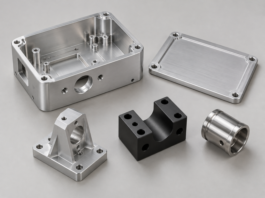
Prototype Parts for Your Next Build
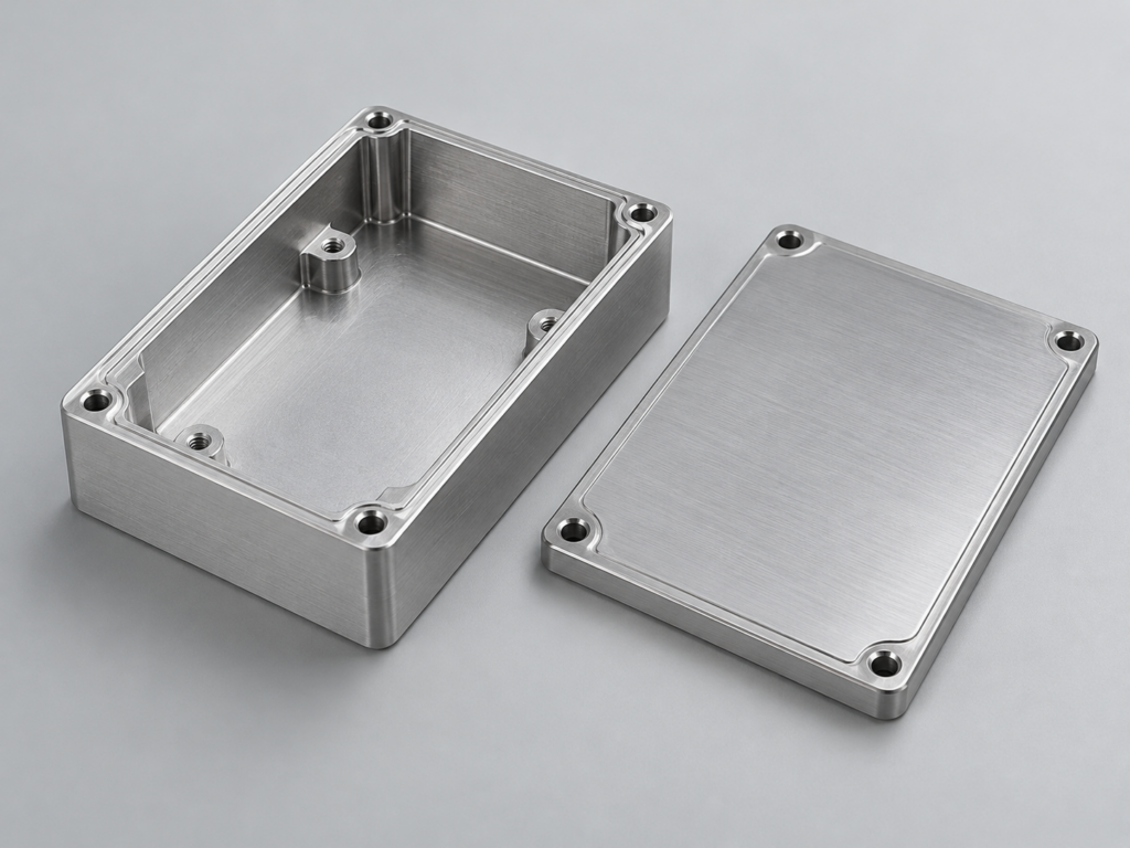
Housings and Covers
Machined pockets, locating bores and mounting faces for instrument mechanisms and equipment assemblies. Use the sample to check internal clearances, the mating cover and the interfaces that locate other components.
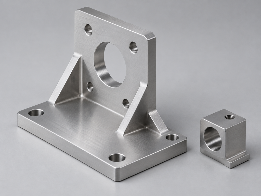
Brackets and Fixtures
Mounting brackets, positioning blocks and fixture plates with defined reference faces and hole locations. Identify the interfaces that matter to installation or repeat positioning so they can be machined and checked against the drawing.
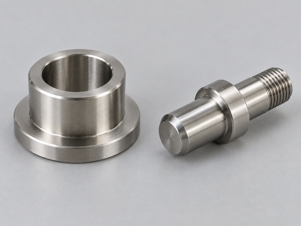
Shafts, Sleeves and Adapters
Turned components for mating diameters, shoulders, threads and mechanical connections. Define the fit, burr limits and relevant surface finish before using the sample in an assembly.
Images on this page are representative part, machining and inspection illustrations.
What Must the Prototype Establish?
Choose the sample around the decision you need to make next. A fit check, a material-dependent functional test and a revised design can need different specifications.
| Next decision | What the sample needs | What to define |
|---|---|---|
| Assembly fit | The mating geometry and relevant interfaces | Reference faces, hole locations, clearances and the condition in which the assembly is checked. |
| Functional behaviour | The specified stock grade, condition and relevant final finish | Operating conditions, critical features and the test method and acceptance criteria. |
| Design iteration | A controlled revision that incorporates the agreed changes | Changed features, unchanged requirements and what the next sample will be used to check. |
CNC prototyping is useful when machined interfaces or a specified stock material matter to the test. Printing can suit an early appearance model or geometry that cutting tools cannot reach. For functional testing, compare the actual material and manufacturing route, rather than treating similar-looking samples as equivalent.
CNC Routes for Different Prototype Geometries
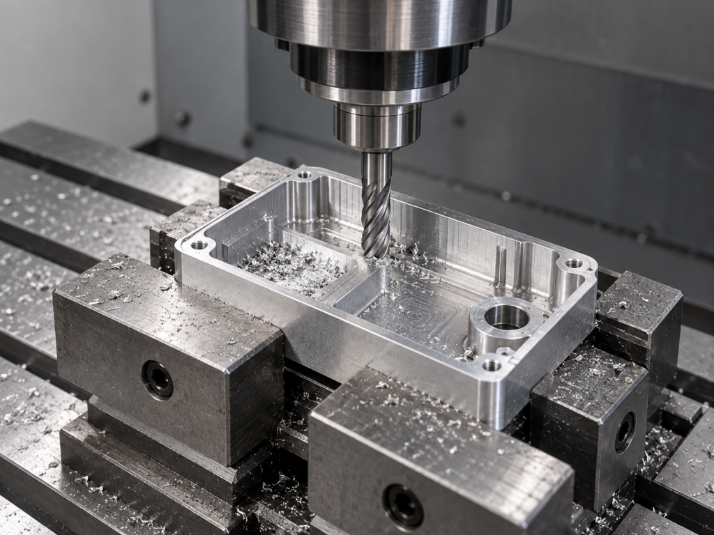
Milled Housings, Plates and Brackets
CNC milling creates pockets, slots, mounting faces and hole patterns in plate, bar or block stock. Tool access, internal corner radii, pocket depth and the surfaces available for clamping affect the route. We review these features before confirming manufacture or any proposed design change.
Explore CNC milling services for more on prismatic parts.
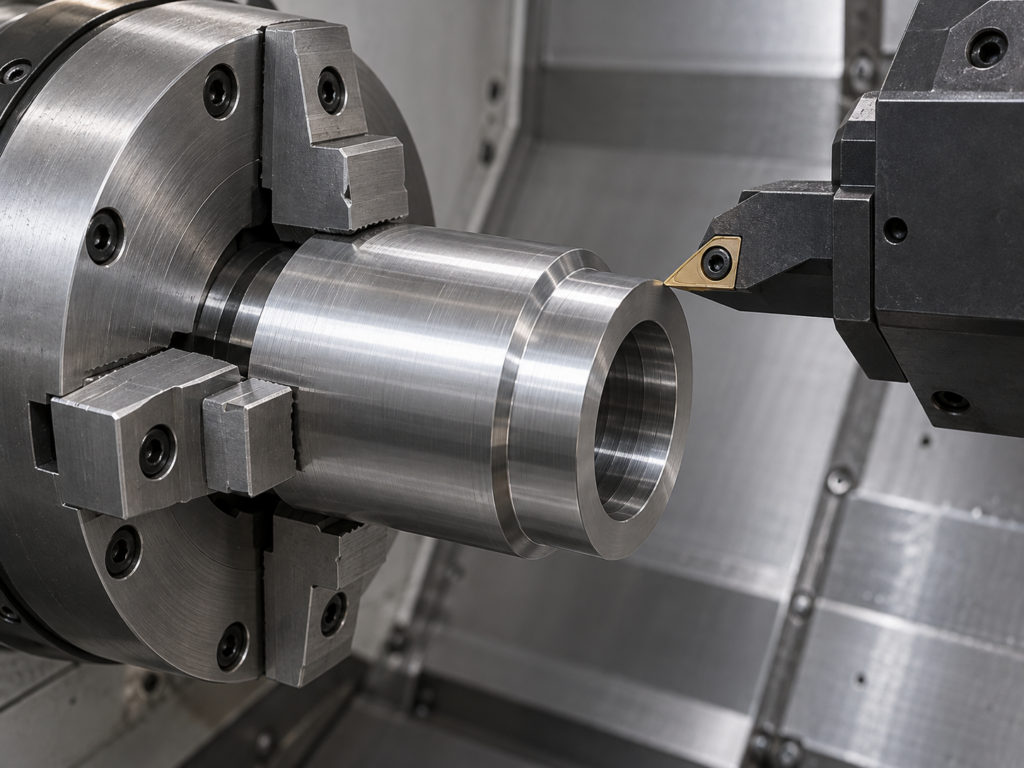
Turned Shafts, Sleeves and Adapters
CNC turning suits rotational features such as bores, diameters, shoulders and threads. Slender sections need suitable support; side holes, flats and slots may require mill-turn work or another setup. The drawing defines which diameters and faces must relate to one another.
Explore CNC turning services for round components.
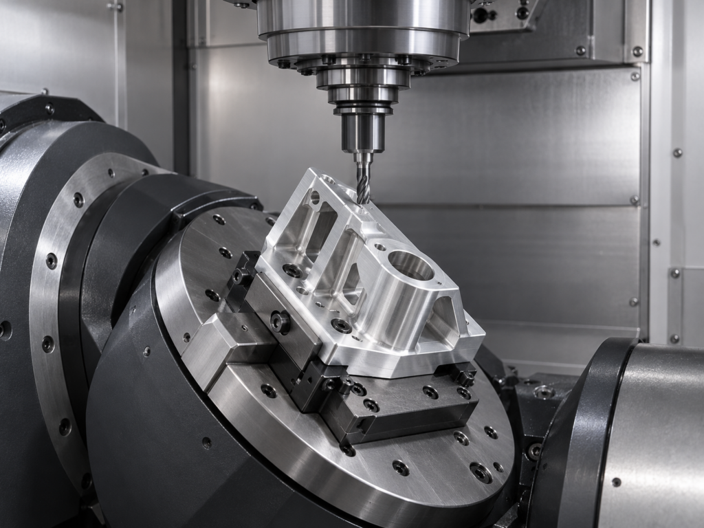
Features Across Several Faces
For angled holes, multiple mounting directions or complex reference relationships, we assess the appropriate multi-face or five-axis route. The choice depends on the part and its datums. Selected ground features, EDM work or other secondary operations are assessed separately, with their inspection requirements included in the quotation.
Materials That Match the Test
Specify the grade and condition used for your test. We machine the agreed material; an alternative grade or product form requires approval.
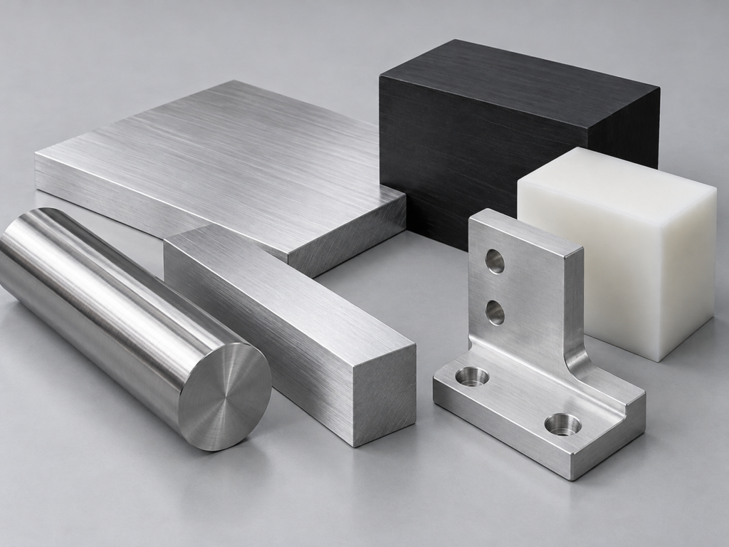
| Material option | Typical prototype parts | Details to keep with the drawing |
|---|---|---|
| 6061-T6 aluminium plate or bar | Housings, brackets and machined adapters | Material standard, stock form, final fit and any anodized appearance requirements. |
| 6082-T6 aluminium plate or bar | Installation plates, fixture blocks and mechanical supports | Specified grade and form, functional-face flatness and measurement condition; approval before substitution for 6061-T6. |
| 7075-T6 aluminium plate or bar | Mechanical prototypes and structural brackets when specified | Material state, intended loading, finish and inspection requirements for the actual design. |
| Specified stainless steel | Shafts, sleeves, connectors and instrument components | 303 is mainly a bar-stock option; 304 and 316L may use bar or plate. Confirm the actual grade, environment and passivation requirements; these grades are not automatically interchangeable. |
| POM-C or POM-H stock | Locating pieces, slides, bushings and contact components | Actual material identity and the agreed measurement state. Material stress, temperature and moisture can affect dimensions. |
Other engineering plastics and metals can be assessed against the project specification. Availability and material-document requirements are confirmed with the quotation; this list does not imply stock on hand.
For more detail on grades, stock form and finished interfaces, see aluminium CNC machining.
Finish the Interfaces You Need to Test
Confirm whether mating dimensions apply before or after finishing. The sample’s surface condition should suit the check you intend to carry out.
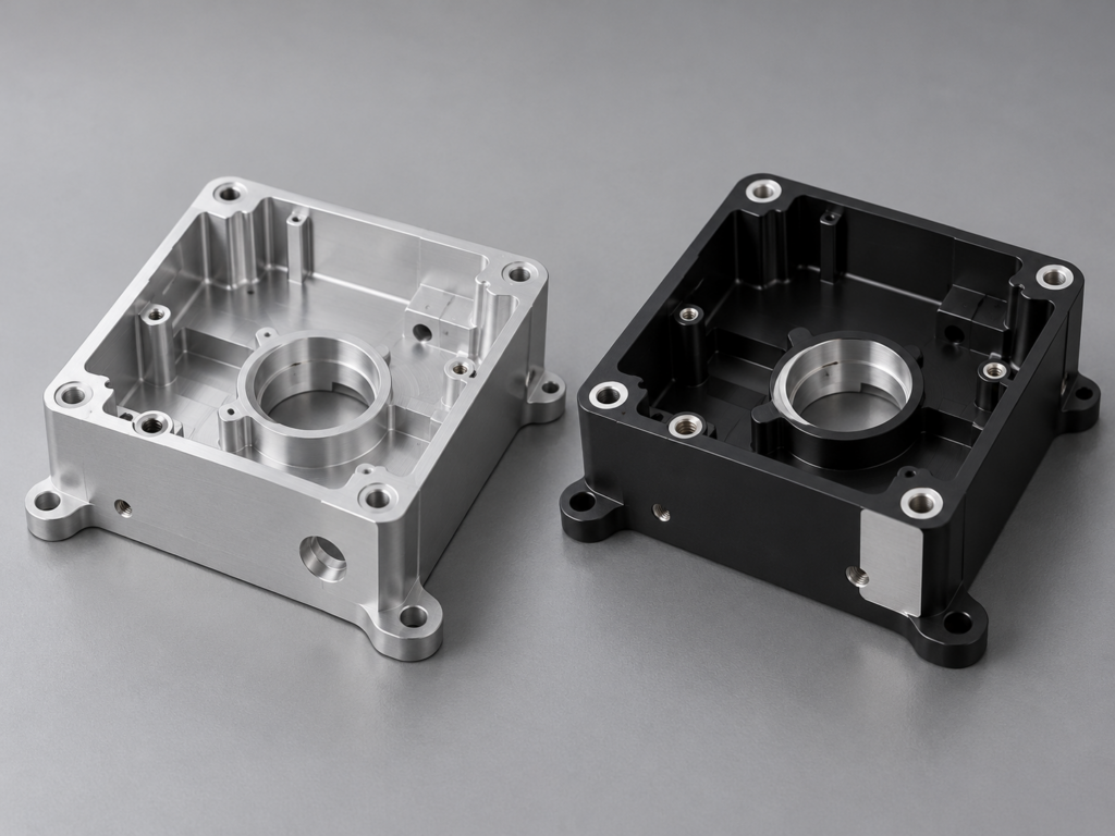
As Machined and Deburred
Retain the machined surface where that condition suits the test. Identify sharp-edge limits and any functional roughness requirement; visible tool marks and a specified surface roughness are separate acceptance questions.
Finished Aluminium Interfaces
For anodized samples, identify cosmetic faces, locating bores, threads and conductive contact areas. Agree masking, the appearance sample where needed and final dimensional inspection. Coating thickness alone is not a universal calculation for the change in every dimension.
Protection, Hardware and Assembly
Specify suitable passivation or protective treatment for the chosen metal. Threaded inserts and simple mechanical assembly can be included with agreed hardware, installation and checking requirements. Specialist finishing is coordinated with selected partners.
Precision and Inspection Around Critical Features
Identify the features that determine whether the prototype fits or can be used for its intended test. The drawing, datums and measurement method govern acceptance.
| Feature type | Assessment range | Conditions |
|---|---|---|
| Selected metal dimensions | To ±0.01 mm after assessment | Stable, accessible features generally no larger than 100 mm; material, geometry, datums and measurement method reviewed. |
| Selected plastic dimensions | Typically ±0.10 mm | Actual material, residual stress, moisture, temperature, support and measurement state affect the result. Tighter selected features require a separate assessment. |
Unmarked dimensions need an agreed general tolerance before manufacture. Tighter ground features are a separate operation; the most demanding tolerance is not a promise for every dimension on the part.
We use suitable dimensional methods, including CMM measurement where the range, probe and method fit the requirement. Reporting can include:
- Agreed critical-feature results linked to the part number and drawing revision.
- Full-dimensional or individual-part reports as a separately quoted scope.
- Formal first article inspection with the required feature numbering, values, tolerances, results and methods.
- Available material documents, order-specific CoC and agreed special-process records.
Routine first-piece checks and a formal FAI package are different deliverables. Define the records your receiving team needs when requesting the quote. See quality and inspection for the wider quality process.
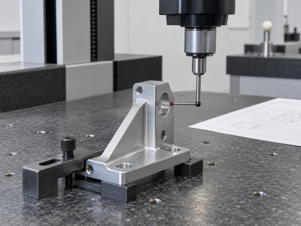
20 Bracket Prototypes in 7075-T6
A robotic end-tool development project required 20 bracket prototypes in 7075-T6, each with a 160 × 100 × 65 mm envelope and mounting features on several faces.
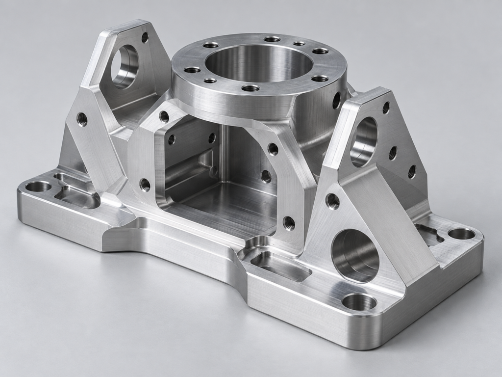
The Required Interfaces
Selected hole diameters carried ±0.02 mm tolerances. Hole position was specified at Ø0.05 mm relative to the defined A/B/C datums, keeping the mounting relationships explicit.
The Manufacturing Route
The customer-approved model incorporated changes in non-critical areas. A five-axis route produced the multi-direction features, with the brackets supplied in the machined condition.
The Delivered Samples
The 20-piece prototype batch was completed in 10 working days, including the agreed dimensional records. Those records addressed the specified part features; application testing is a separate project step.
Geometry illustration of this prototype type.
Prototype Lead Time and Quotation
The schedule depends on the sample’s geometry, quantity, material, finishing and inspection work.
| Prototype order | Typical manufacturing lead time | Included conditions |
|---|---|---|
| Simple aluminium or POM parts | 5–7 working days | Available stock, 1–10 pieces, normal tolerances and deburring. Special finishes are additional. |
| Complex or multi-face prototypes | 8–12 working days | Typically 5–20 pieces; special material sourcing and heat treatment are scheduled separately. |
The manufacturing clock starts once the technical and order requirements, necessary payment and material availability are confirmed. Common specialist finishing typically adds 3–5 working days; special processes are scheduled separately. Customer approvals or later revisions have their own schedule. Manufacturing lead time excludes transit and customs clearance.
A one-off part still needs programming, setup, fixturing and first-piece checks. Tool access, material removal, tight features, specialist finishes and reporting add work. Give the sample quantity and any alternative quantities together so each can be quoted against the same revision and requirements.
From Enquiry to Inspected Samples
1. Describe the Next Build
Share a useful part description and what the sample needs to establish. Add the current model or drawing, quantity and known requirements when available.
2. Confirm the Quotation
We clarify the manufacturing route, material, finish, price, inspection deliverables and schedule. Any proposed geometry or specification change needs approval before manufacture.
3. Machine and Finish
Parts follow the approved requirements through machining and the agreed finishing or hardware operations. First-piece and process checks address the planned features.
4. Inspect and Dispatch
Final checks, labels and documents follow the order’s agreed scope. Parts are identified by the applicable part number, revision, quantity and batch for shipment.
Your Next Revision or First Batch
When the Design Changes
Identify the trial finding and affected feature, then send the current model and drawing with the new revision. Distinguish changed geometry, material, finish or inspection requirements from those that remain the same. If the model and drawing disagree, we clarify the controlled requirements before the next sample is made.
When the Sample Is Approved
Keep the approved drawing revision with the inspection requirements. Confirm the next quantity, material and finish, required records, packing and delivery plan. A different quantity can justify a different manufacturing route, which is reviewed before production.
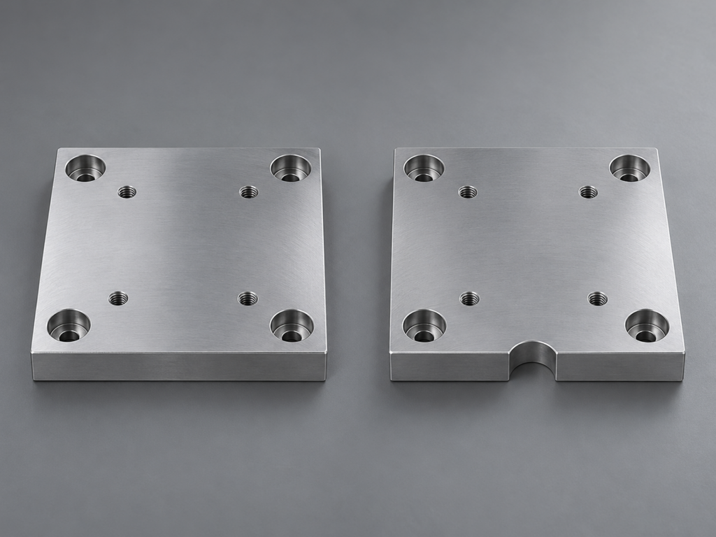
Representative geometry-change illustration.
CNC Prototype Questions
Start Your CNC Prototype Project
Your name, work email and a useful part description are enough to start. If known, include the sample quantity and what the next build needs to test.
Helpful details for quotation:
- Current CAD model and controlled drawing revision, with the changed features identified for a revision.
- Material grade, condition and stock form, or the operating requirements if material is undecided.
- Critical dimensions, datums, finish, masking, hardware and inspection-document needs.
- Quantity options, delivery country and the target dispatch or arrival date.
Upload non-confidential PDF drawings directly, or place CAD files such as STEP in a ZIP archive, up to 5 MB per file. Your quotation sets out the manufacturing route, agreed deliverables, price and confirmed manufacturing schedule.
Discuss an NDA and file transfer before sharing restricted drawings.