Aluminium CNC Machining
Get aluminium brackets, baseplates, housings and turned adapters made to your drawings for equipment and instrument assemblies. Great Machining combines in-house CNC machining, dimensional inspection and partner finishing to deliver parts with the specified final fit and records.
From a single prototype to planned repeat batches, start with your drawing or part description.
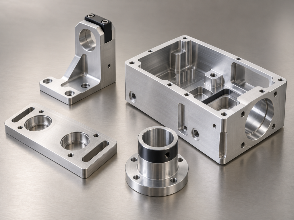
Aluminium Parts for Your Equipment
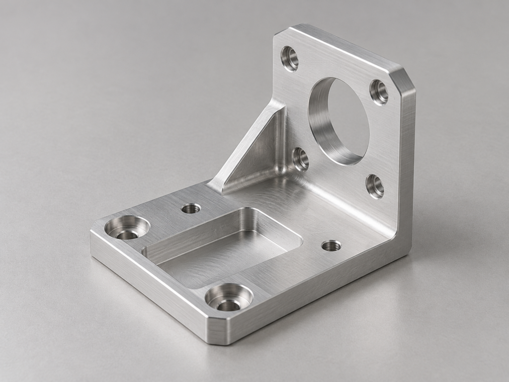
Brackets
6061-T6 plate or bar, milled into mounting faces, fixing holes and pockets for sensors, cameras and equipment assemblies.
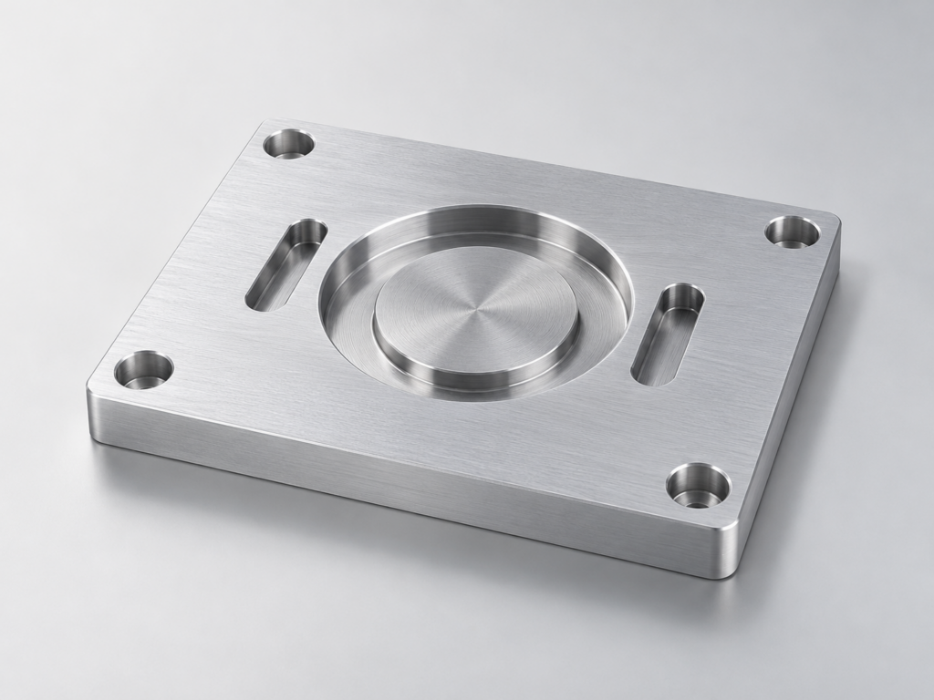
Baseplates
6082-T6 plate with mounting holes, slots and a defined reference face for positioning fixtures or equipment modules.
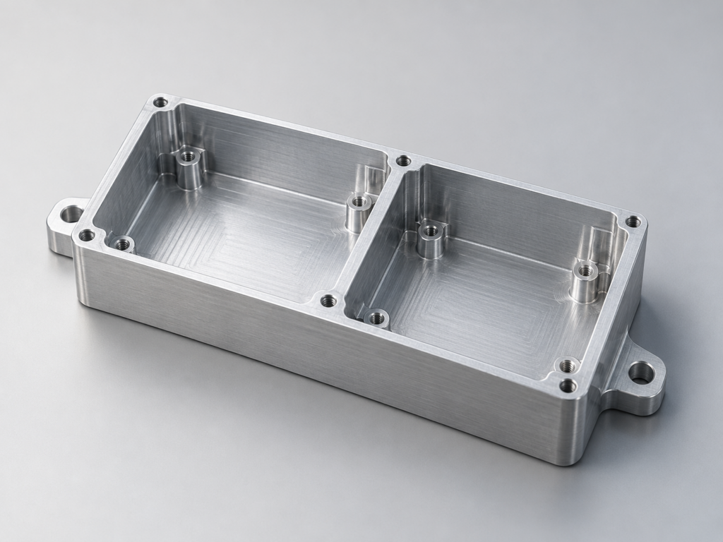
Housings
6061-T6 plate or bar with internal pockets, locating bores and mounting interfaces for instrument mechanisms.
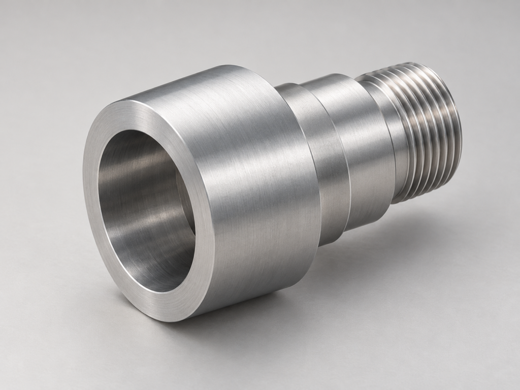
Turned Adapters
6061-T6 bar, turned and drilled for bores, shoulders and threads that connect mechanical assemblies.
Representative part illustrations.
Choose the Grade, Temper and Stock Form
We supply machined parts in the material specified for your design. Grade, temper and product form stay linked to the drawing; an alternative requires your approval.
For housings, brackets, fixtures and adapters. Plate suits pocketed bodies and mounting faces; bar suits compact milled parts and turned interfaces.
We quote the specified material standard and T6 condition. Visible anodized faces need an agreed colour and appearance; source-material documents can be included in the order.
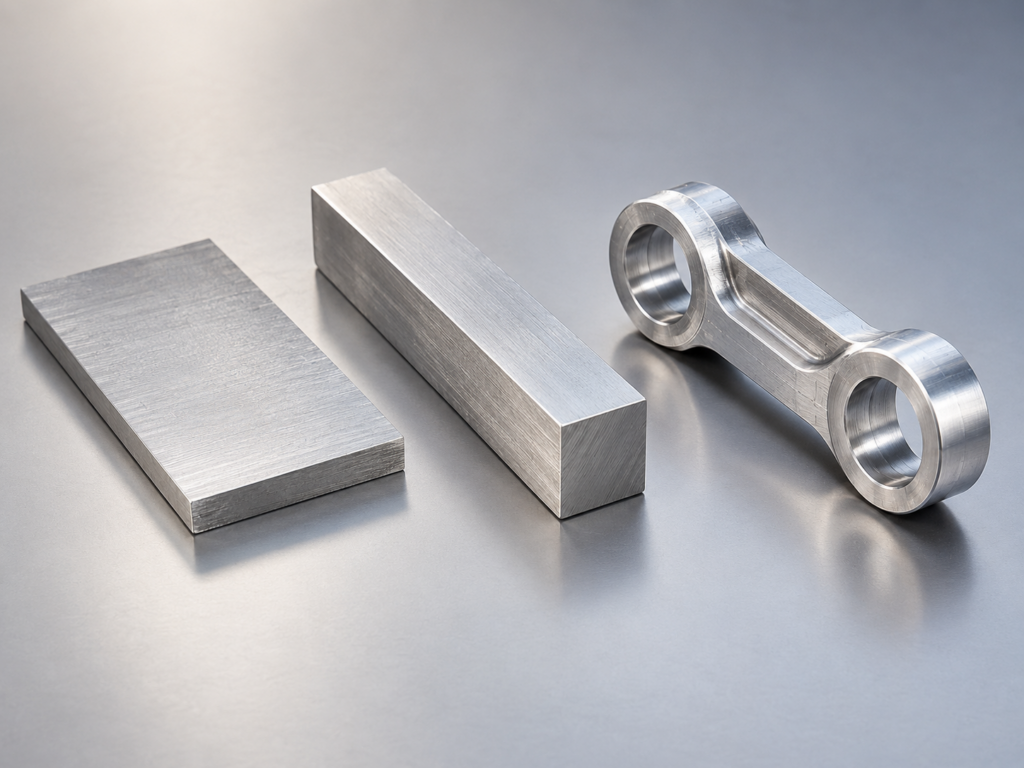
An option for equipment installation plates, fixture blocks and mechanical supports where the drawing calls for 6082-T6. Wide functional faces need a defined flatness area and measurement condition.
6082-T6 requires approval as an alternative to 6061-T6. Functional anodizing does not ensure decorative colour consistency. For visible parts, agree the stock form and an appearance sample; assess the actual plate or bar supply separately from extruded 6082.
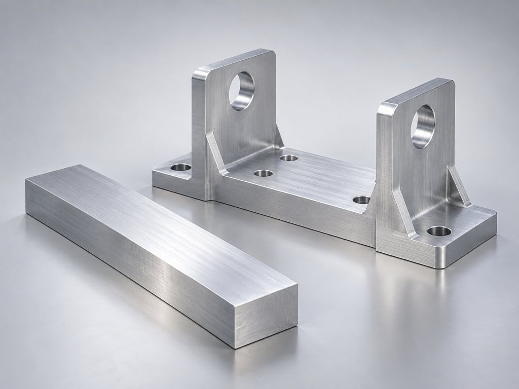
For mechanical prototypes and structural parts with higher strength requirements. We quote this option against the specified load requirements, temper, surface treatment and inspection needs. Availability is checked for the project.
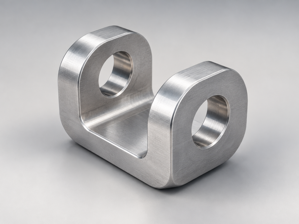
For long enclosures, guides and frames with a continuous cross-section. Specify the temper, profile, straightness and cut length; CNC machining adds end faces, mounting holes and threads. Profile tooling and minimum purchase weight affect the order.
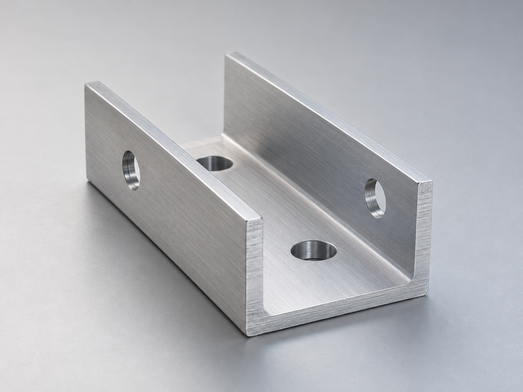
For folded covers, enclosures and sheet brackets. This is a sheet-fabrication choice through our production partners, rather than the default for a solid CNC body. Thickness, bend direction and final coating govern suitability.
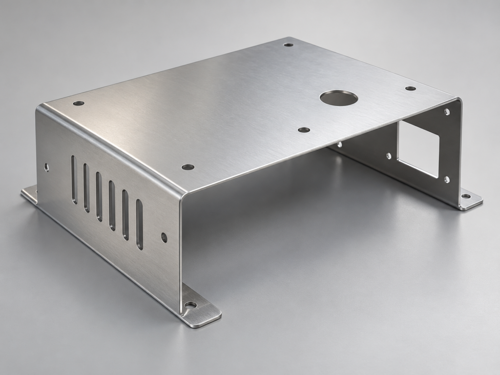
Material availability and document level are confirmed in the quotation; these options do not imply stock on hand.
Milling, Turning and Complex Aluminium Features
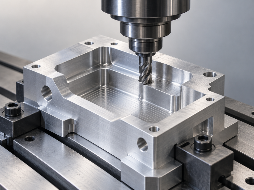
CNC Milling
Pockets, slots, hole patterns and flat mounting faces in plate or bar.
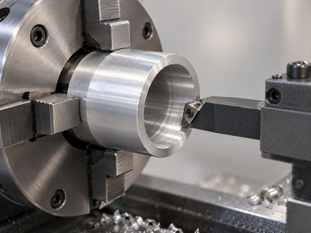
CNC Turning
Bores, diameters, shoulders and threads in cylindrical adapters and sleeves.
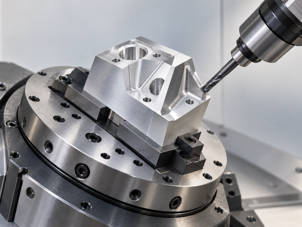
Five-Axis Machining
Angled mounting features and accessible surfaces on several orientations.
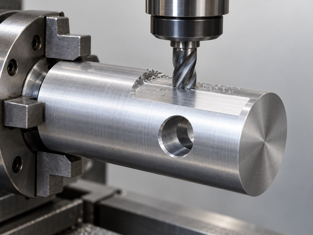
Mill-Turn Machining
Round bodies with cross-holes, flats or transverse features.
| Capability | Part or feature range | Conditions |
|---|---|---|
| Three-axis milling | Typically up to 1,000 × 600 × 400 mm | Part envelope; stock, fixture, tool access and weight affect suitability. |
| Five-axis machining | Approximately Ø300 × 250 mm | Grippable small and medium complex parts; angles and surfaces assessed individually. |
| CNC turning | Approximate outside diameter 3–250 mm; length up to 600 mm | Minimum diameter and maximum length cannot be combined; slender parts need suitable support. |
| Selected precision features | Down to ±0.01 mm after assessment, normally on features no larger than 100 mm | Material stability, geometry, datums and measurement method govern feasibility; not every dimension. |
Explore CNC milling services or CNC turning services for more process detail.
Keep Functional Features Stable Through Machining
CNC machining removes material from stock to create the part’s features. Heavy removal and clamping can change its shape; a part that measures correctly while held may move after release.
Stock → Roughing → Finishing → Measurement
Match stock condition to the drawing, remove bulk material, then finish functional features with suitable support. Define whether acceptance applies to the released part or an agreed supported condition. The instrument housing project below used separate roughing and finishing operations.
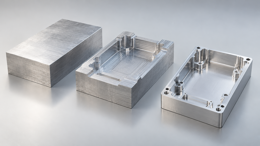
| Geometry | What affects the result | Useful drawing detail |
|---|---|---|
| Thin walls | Wall height, unsupported area and cutting forces | Wall thickness, functional faces and allowable movement. |
| Wide baseplates | Stock condition, uneven removal and clamping | Flatness area, datums and measurement support. |
| Deep cavities | Tool reach, wall support and material removal | Pocket depth, corner access and critical internal features. |
Finishes, Appearance and Final Fit
Choose the finish around the assembled part. We coordinate specialist finishing with production partners and define which surfaces remain functional, visible or conductive.
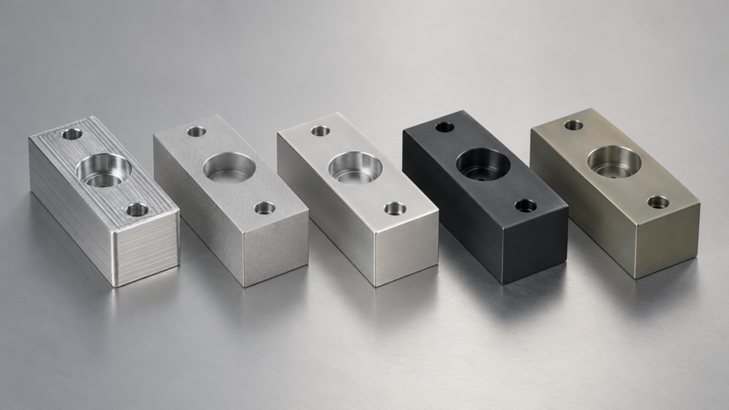
| Finish | Main purpose and appearance | Fit and contact zones | Acceptance |
|---|---|---|---|
| As machined and deburred | Cut surfaces retain tool marks; edges finished to drawing | Specify roughness on functional faces and edge requirements | Dimensions and marked surfaces after machining. |
| Bead blasted | Agreed texture on visible faces | Protect bores, threads and other sensitive zones as needed | Approved texture sample and protected features. |
| Decorative anodized | Natural or agreed colour for suitable aluminium | Define masking on locating fits and conductive contacts | Agreed appearance sample and final dimensions after treatment. |
| Hard anodized | Wear-oriented treatment on suitable functional surfaces | Agree final fit, coating extent and any masked zones | Specified final dimensions, sealing and colour requirements. |
| Conversion film | Protection, paint preparation or specified conductive contact needs | Select the required system and contact areas | Agreed process specification and final features. |
For the illustrated housing, the locating bore and contact pad are masked while the visible exterior is finished. Mark these zones on the drawing. A nominal film thickness alone does not define a universal allowance for bore or shaft diameter.
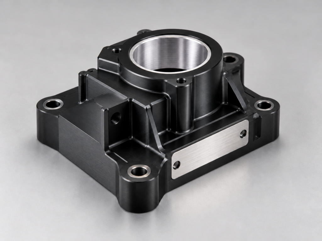
Instrument Housing: From Machining to Final Inspection
Twelve 6061-T6 prototype housings for an industrial measurement instrument combined locating accuracy with an approved black anodized appearance.
Requirements
Each housing measured 120 × 80 × 35 mm. The selected locating bore was Ø20.000–20.020 mm; the 100 × 70 mm mounting face required 0.03 mm flatness under the agreed support and measurement conditions.
Manufacturing and Finish
We separated roughing from finishing, masked the locating bore and specified contact zones, and coordinated the black anodizing to the approved appearance sample.
Inspection and Dispatch
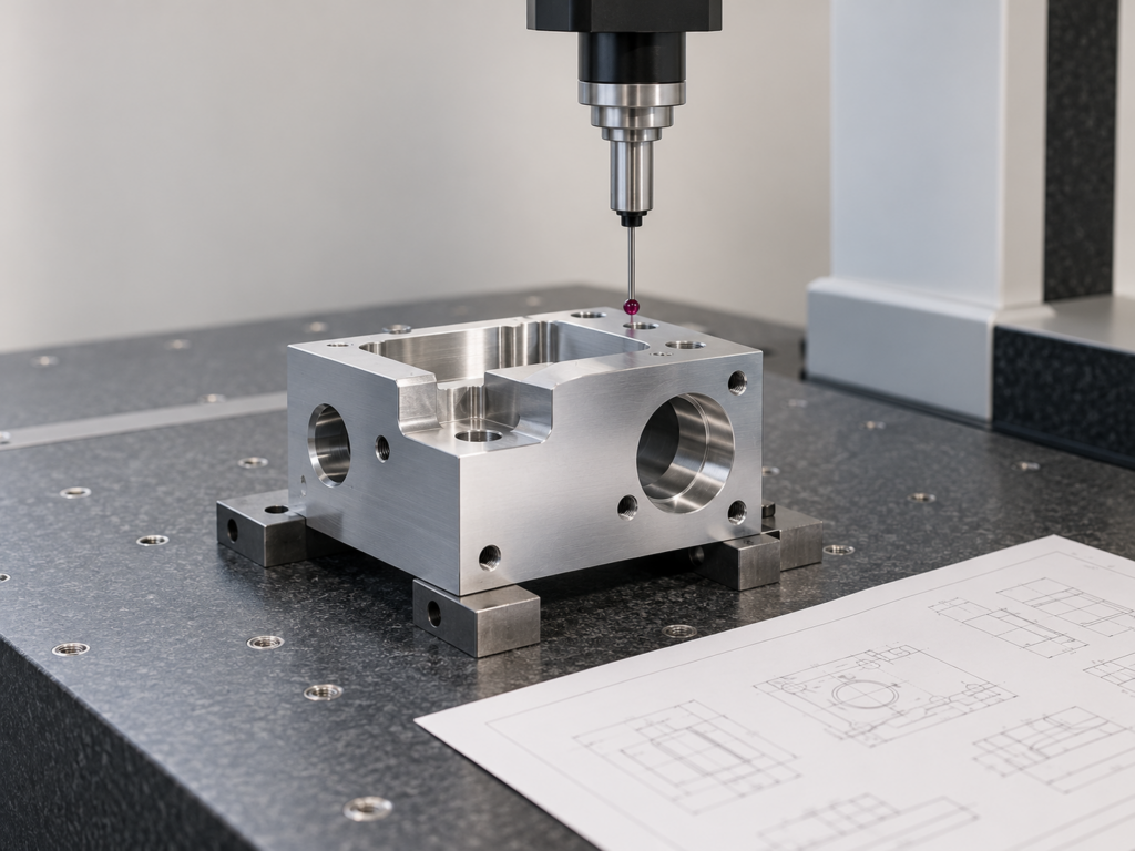
The twelve housings completed the agreed dimensional and fit checks, including CMM inspection of agreed features. Machining took eight working days; partner finishing and final inspection took three more. Dispatch followed eleven working days after the project start, excluding shipping.
A later 200-piece batch was planned; it had not been completed as part of this project.
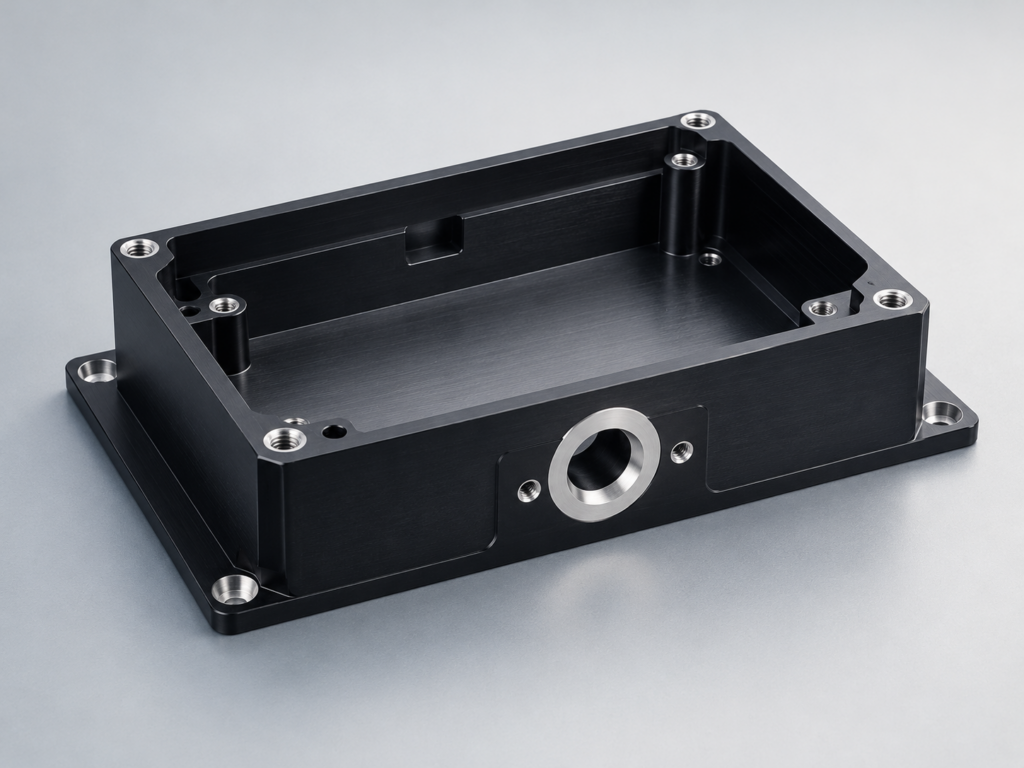
Representative illustration of the anonymized housing project.
Specify the Documents Your Order Needs
Select the records required for your receiving inspection. We link agreed results to the part number, drawing revision, measured characteristics and applicable batch.
| Deliverable | What it provides | Order detail to agree |
|---|---|---|
| Critical-dimension report | Results for the characteristics listed in the quotation | Feature numbers, tolerances and measurement method. |
| Full-dimension or each-part report | Wider dimensional coverage or individual part records | Coverage, quantity and reporting effort, quoted separately. |
| First article inspection (FAI) | Agreed first-article record with numbered features, nominal values, tolerances, results and methods | Drawing revision, ballooning and required format. |
| Source-material documents | Source records or available material proof | Grade, temper, form and required document level before procurement. |
| Certificate of Conformity (CoC) | Declaration against the agreed part and order requirements | Required references; a CoC is not an independent laboratory certificate. |
| Special-process records | Agreed records for anodizing or other specified processes | Process specification and available partner documentation. |
No single certificate level or inspection coverage applies automatically to every order. See our quality control approach.
Why Source Aluminium Parts from Great Machining
Combine Forming with CNC When the Part Calls for It
Machining from plate or bar suits changing designs and parts without dedicated forming tools. A stable repeat design may benefit from a shaped starting blank.
A heated solid aluminium billet is pressed through a die to form a continuous profile. Our partners supply the extrusion; CNC machining adds accurate end faces, holes, threads and mounting interfaces.
For long housings and frames, compare profile tooling, minimum purchase weight, specified alloy and temper, straightness, cut length and finish. The repeated section must suit the design.
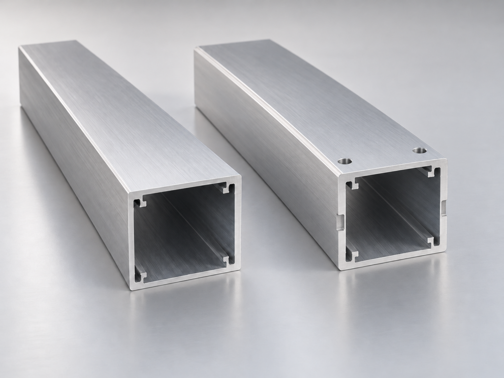
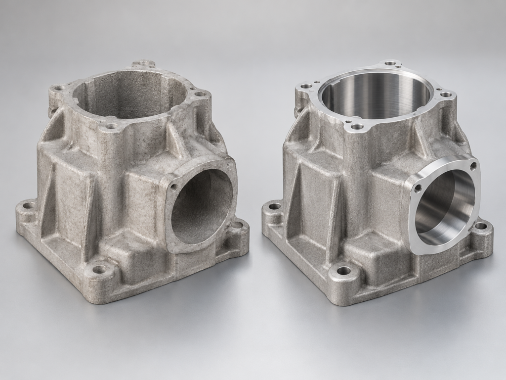
A formed aluminium blank can reduce repeated bulk machining in housings and hardware. We coordinate partner casting and CNC finishing of functional interfaces.
Assessment typically starts from 500 pieces per batch; this is not a universal cost break-even point. Alloy, tooling, porosity requirements, machining allowance, appearance and inspection all affect the quotation.
Where Aluminium Fits Your Application
Lower Moving Mass
Useful for moving brackets and equipment assemblies when load, stiffness and vibration requirements are satisfied by the designed section.
Environment and Corrosion
Match the alloy and protective finish to moisture, chemicals and service conditions. The application determines the protection needed.
Thermal Interfaces
Aluminium can conduct heat through bases and housings. Contact area, flatness, joining and coatings influence the assembled thermal path.
Machined Detail and Electrical Contact
Machinability supports pockets, holes and mounting features. Where grounding or conductive contact matters, specify contact zones and a compatible finish.
More Aluminium Part Geometries
Representative illustrations of material, feature and application combinations.
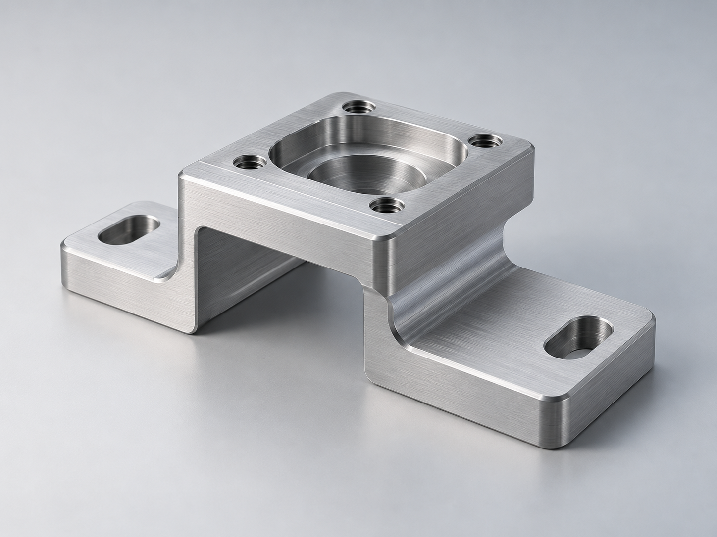
Stepped Sensor Mounting Bracket
6061-T6 plate or bar · Stepped faces and fixing holes for equipment sensor or camera mounting.
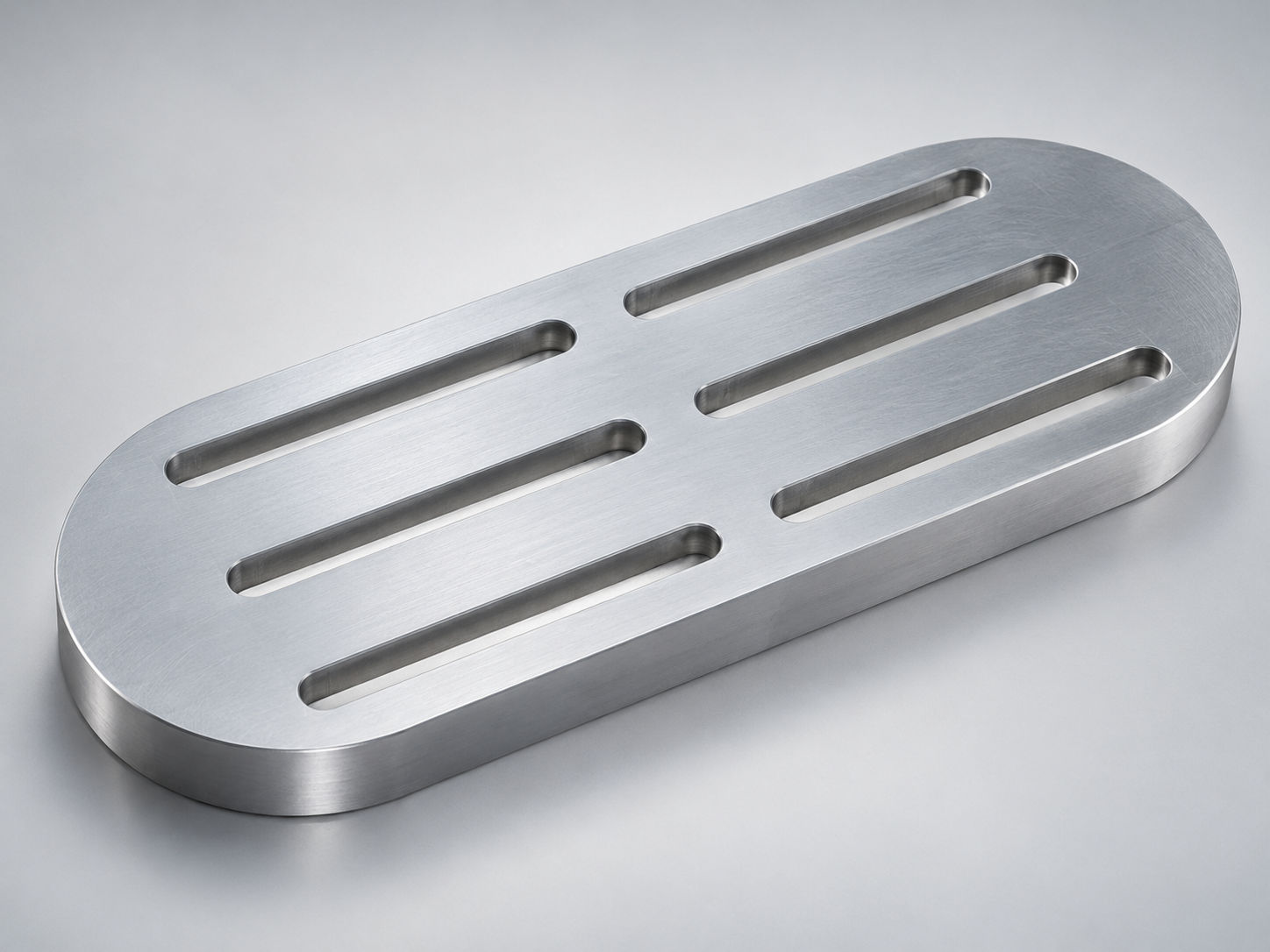
Slotted Equipment Baseplate
6082-T6 plate · Mounting slots and a broad functional face for equipment installation or positioning.
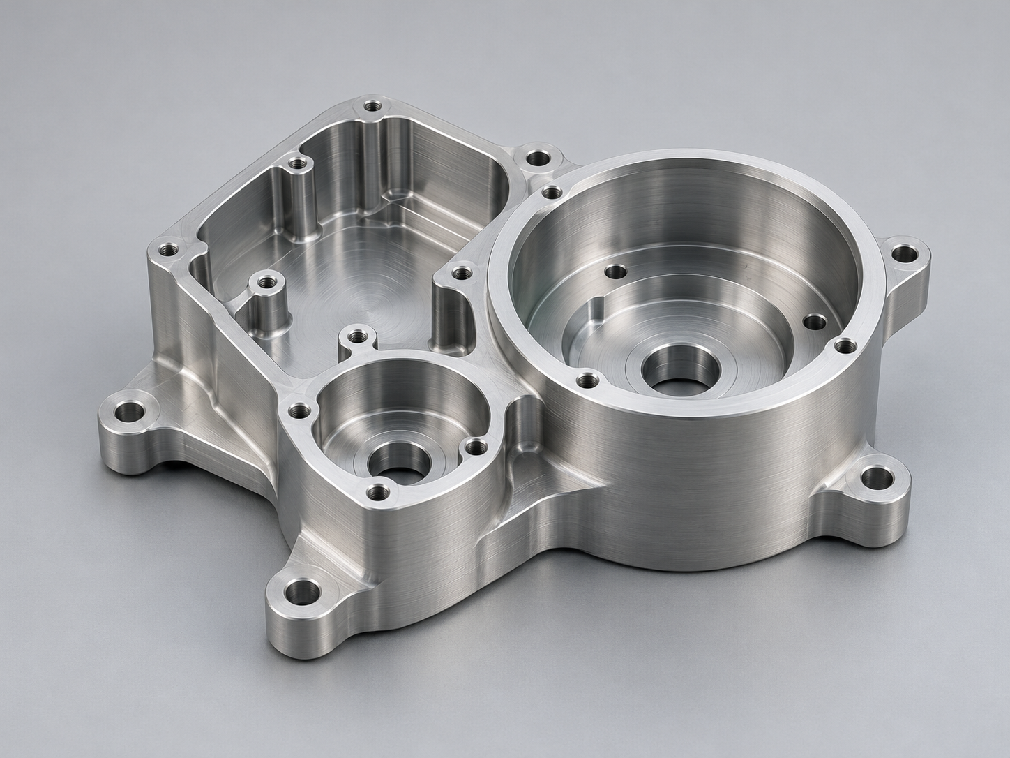
Pocketed Instrument Body
6061-T6 plate or bar · Internal pockets and mounting interfaces for an instrument housing.
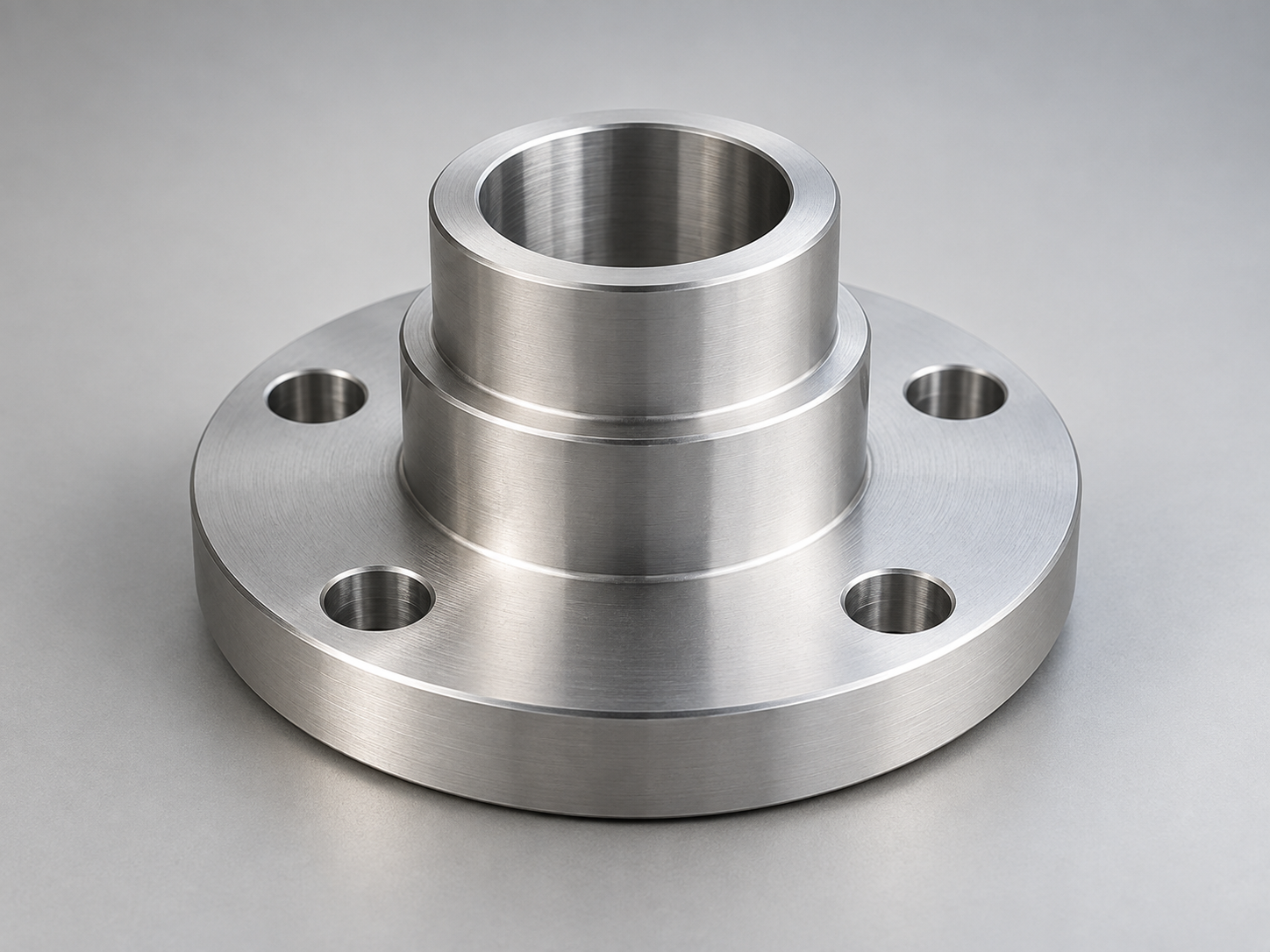
Flanged Turned Adapter
6061-T6 bar · Bore, shoulder and flange for a mechanical connection.
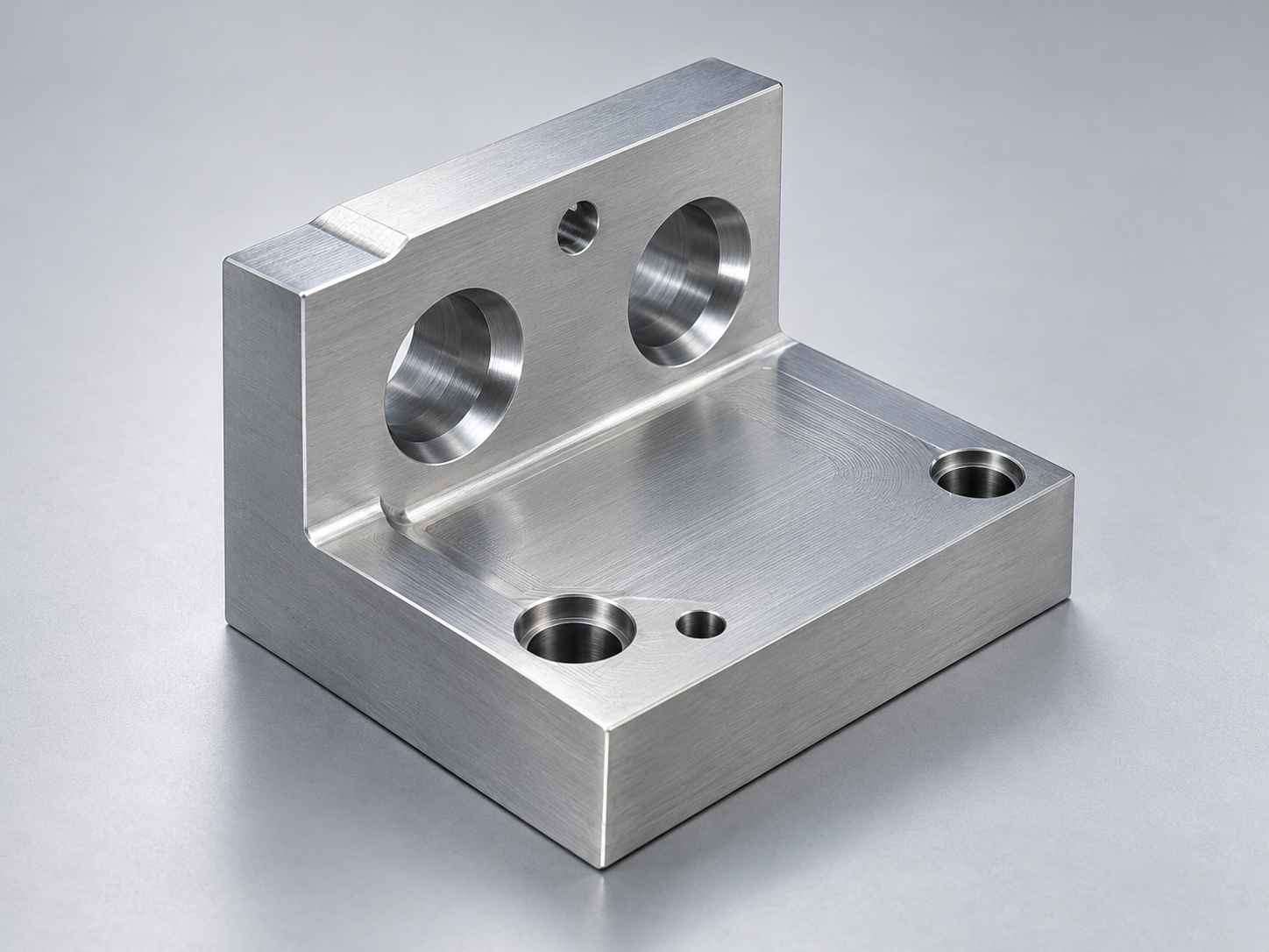
Aluminium Fixture Block
6082-T6 plate or bar · Locating holes and reference faces for workholding or equipment positioning.
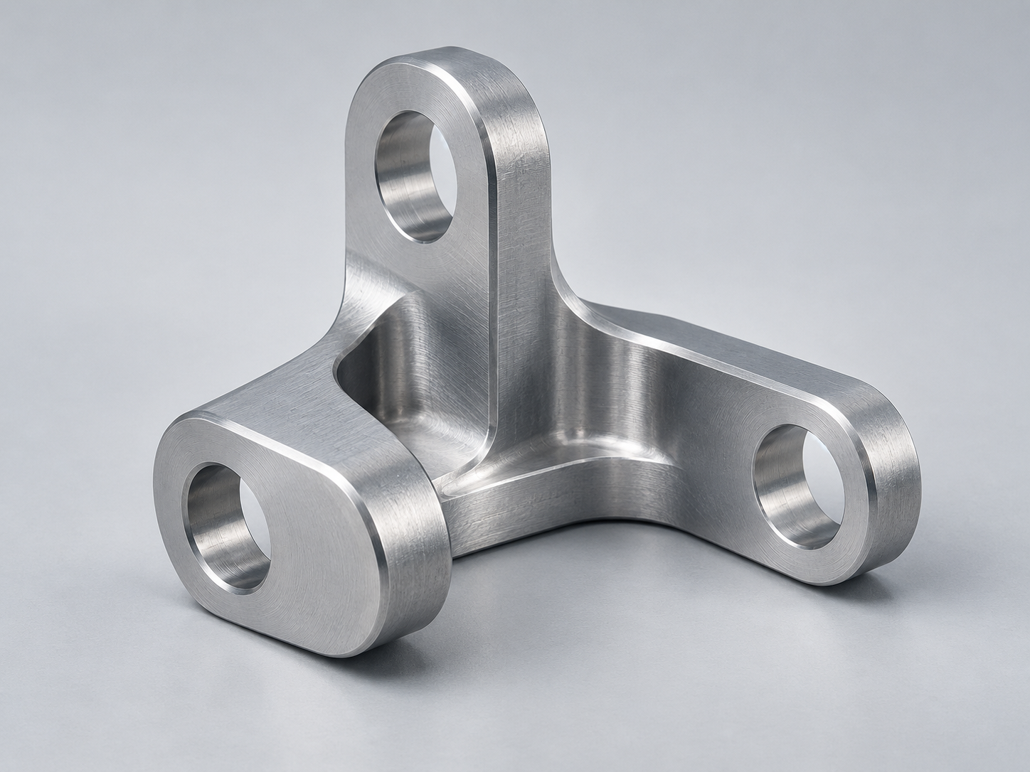
Multi-Direction Mechanical Bracket
Project-specific 7075-T6 plate or bar · Features on several orientations for a mechanical prototype or structural bracket.
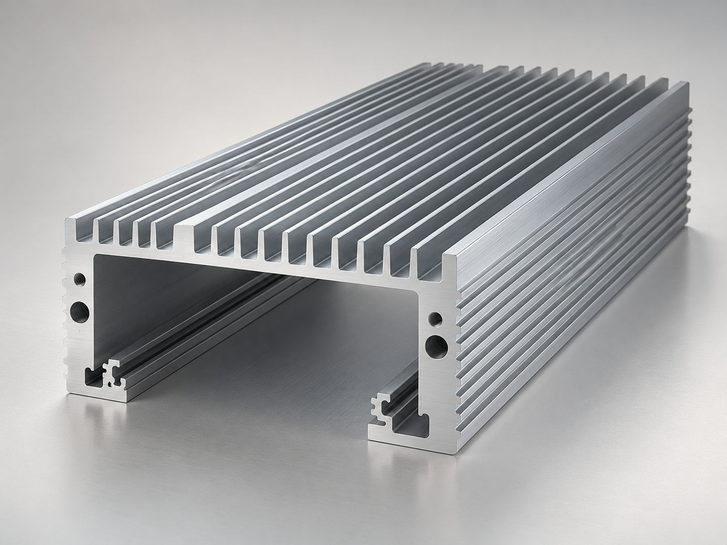
Extruded Enclosure Section
6063 in the specified temper · Continuous profile with machined ends and interfaces for an enclosure or equipment frame.
From Prototype to Planned Repeat Orders
Timing starts after technical and order requirements are confirmed. Common specialist finishing typically adds 3–5 working days; special processes are scheduled separately. International shipping is additional.
Aluminium Machining Questions
Send Your Aluminium Part for a Quote
Enough to Start
Your name, work email and a useful part description are enough for an initial inquiry. Add quantity or program stage when known. Non-confidential PDF or ZIP drawing files are optional.
Helpful for Quotation
- CAD and the controlled drawing, with critical dimensions, tolerances and final fits.
- Grade, temper and stock form, or operating use if material is undecided.
- Surface finish, appearance and masking requirements.
- Document needs, packing, delivery country and target date.
Share whichever details you have; the remaining requirements can be agreed during quotation.
For an NDA or confidential information, contact us before sharing files.