CNC Machining Services
Custom metal and engineering plastic parts, made to your drawings—from a functional prototype to a repeat production batch. Great Machining combines in-house milling, turning, five-axis and mill-turn machining with agreed finishing and dimensional inspection for equipment and instrument components.
One part or a mixed list of housings, brackets, shafts, sleeves and fixtures.
Material, critical dimensions and final surface requirements reviewed together.
An engineering quotation with the manufacturing route, scope and schedule.
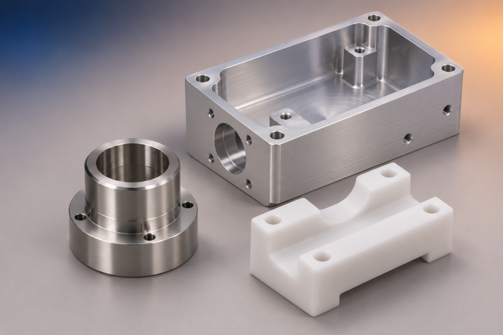
Illustrative CNC parts
36
primary CNC machines
Four
CNC process families
Metal + plastic
engineering parts
Order-specific
inspection
In-house machining. Clearly defined project scope.
Our CNC equipment comprises 18 three-axis machining centres, four five-axis centres, 10 CNC lathes and four mill-turn machines. Dimensional inspection, deburring, simple fixtures, insert installation and agreed mechanical assembly are also handled in-house. Specialist treatments, including anodising, plating, passivation and heat treatment, are arranged through selected partners.
The quotation identifies the route and deliverables for your parts. Tell us at the outset if your purchase requires a specified manufacturing location, restrictions on subcontracting or a supplier audit.
Choose the CNC process around your part
Process images show illustrative parts.
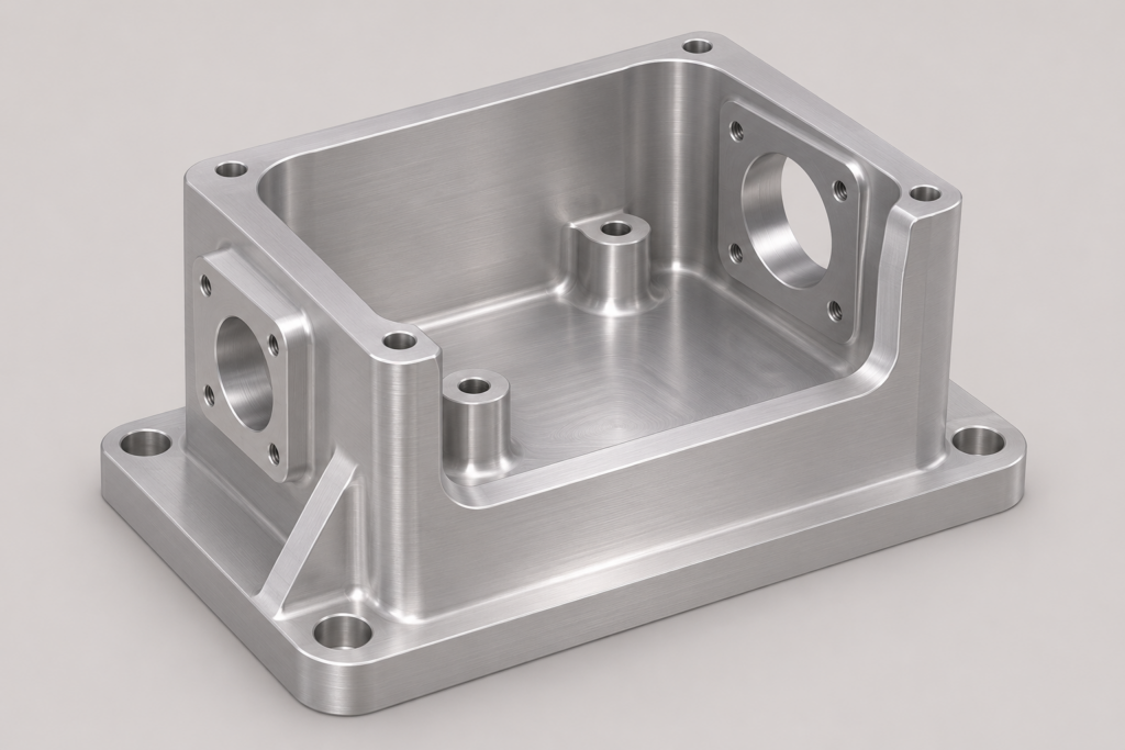
CNC milling
For housings, mounting plates, brackets and fixtures with pockets, holes and flat reference surfaces. Milling is a practical starting point for block and plate components; the number of accessible faces and their relationship to the drawing datums determine the setups. Deep pockets and tall thin walls need particular attention to tool access and support.
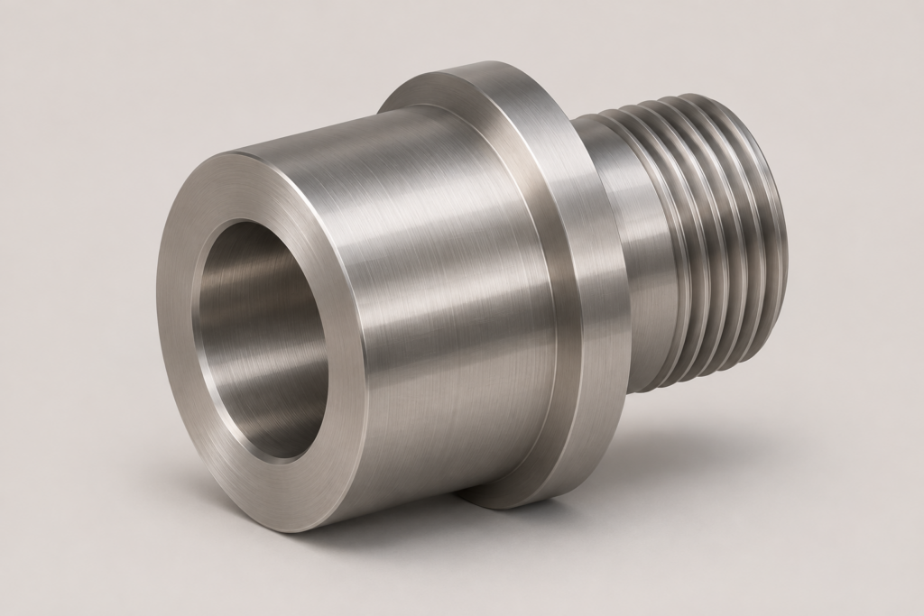
CNC turning
For shafts, sleeves, rings, spacers and threaded connectors built around a rotational axis. Turning suits concentric diameters and end features. Long, slender parts need support, and a close diameter tolerance does not by itself define roundness, runout or the relationship between separate features.
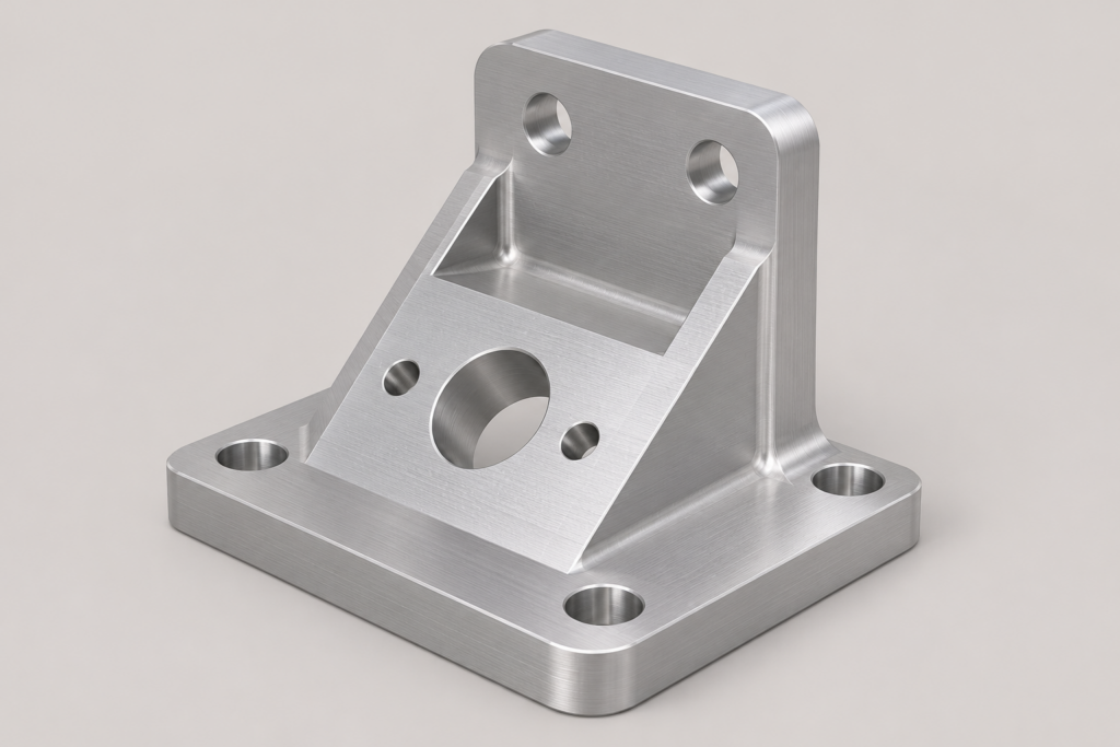
Five-axis machining
For smaller complex brackets, angled interfaces and accessible curved surfaces. Orienting the part towards the cutting tool can improve access to features on several faces and reduce repeated repositioning. The useful route depends on the clamping area, tool reach and datum relationships; five-axis machining is not automatically the lowest-cost choice for a simple part.
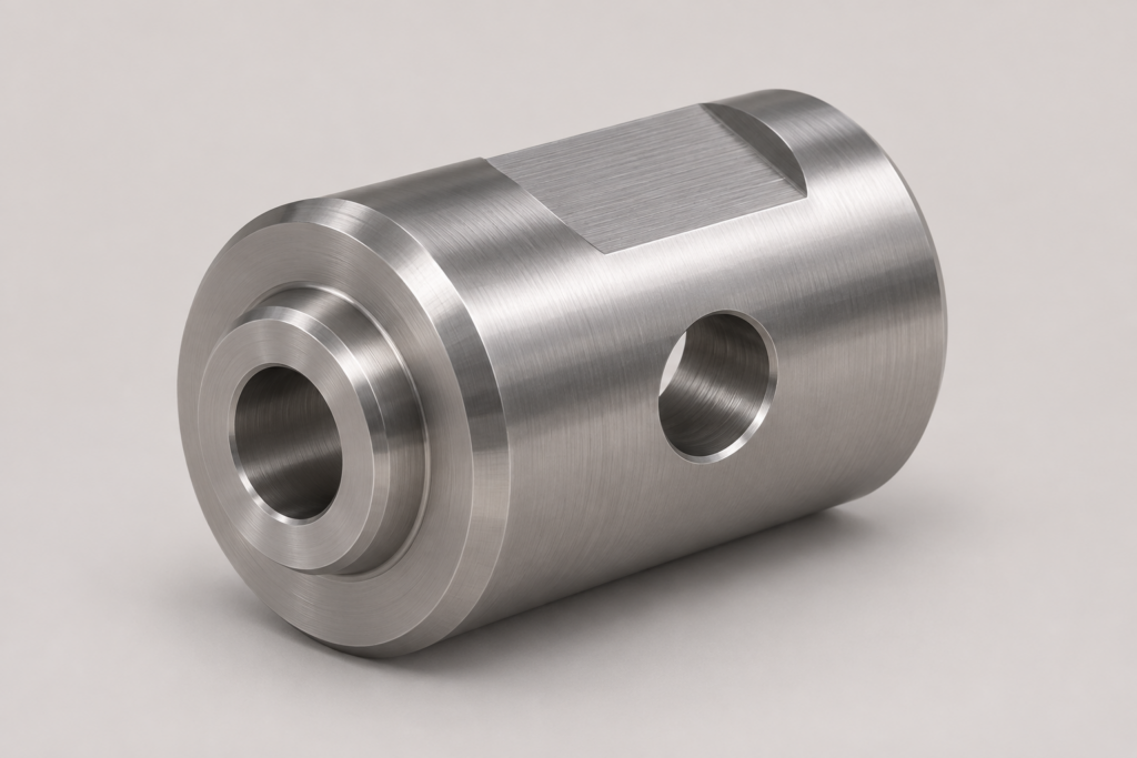
Mill-turn machining
For a cylindrical body with side holes, slots, flats or other milled features. Combining turning and milling can reduce transfers between machines and help manage relationships between rotational and off-axis features. We review the actual feature combination and workholding before selecting this route.
Supporting operations: In-house wire EDM and sinker EDM address selected profiles and cavities in electrically conductive materials; local grinding supports selected finishing requirements. These operations are assessed for the specific part rather than included in every CNC route. Sheet metal, moulding, additive manufacturing and other additional processes are available through selected production partners when a project needs them.
One coordinated route for a mixed part list
An equipment assembly may combine an aluminium housing, a stainless steel shaft and a POM guide. Our custom CNC machining service brings those different material, finishing and inspection requirements into one coordinated enquiry.
Great Machining coordinates the drawings, process sequence and delivery through one project contact. Part numbers and revisions stay attached to the relevant requirements, while specialist-process requirements are passed to the production partner. Agreed incoming or return inspection checks the features affected by those operations.
For purchasing teams, that means a quotation which makes clear what is included for each item, which operations use partners and which documents accompany delivery. If quantities or delivery dates differ by part, flag them in the list so they can be priced and scheduled accordingly.
From drawings to delivered parts
1. Send the project
Share the drawings or CAD you have, the quantity and what the part needs to do. A STEP or IGES model plus a dimensioned PDF is useful for defining geometry, tolerances, threads and finish. You can also begin with a description if a material or process is still undecided.
2. Review the manufacturing route
We review material availability, tool access, critical features, finish and inspection needs. Where CAD and PDF disagree, the controlling revision and requirement must be resolved before production. Any proposed design change is returned for your approval.
3. Confirm the quotation and release
The engineering quotation sets out the agreed route, quantity, price, tooling or fixture charges where applicable, finishing, inspection documents and manufacturing lead time. Production follows confirmation of the controlled requirements, order conditions and material availability.
4. Machine, inspect and dispatch
Parts move through machining, agreed specialist treatments and inspection. Packing lists and part labels identify the part number, revision, quantity and applicable batch. Shipping arrangements and any required approval stage are scheduled separately from manufacture.
For a multiple-part RFQ: Use one BOM line per part number and revision. Match each line to its CAD/PDF filenames, material and condition, finish, quantity and required documents. Separate prototype quantities from later batch or annual estimates. Add shared assembly notes, packing requirements, target dates and the receiving country once for the project.
Inspection matched to the features that matter
A locating bore, a mounting plane and a cosmetic face need different checks. Identify the functional dimensions and drawing datums so the inspection method can suit the requirement. Our resources include CMM, optical measurement, surface roughness measurement and conventional gauges, used within their applicable measurement ranges and conditions.
Measurement access, probe or gauge suitability, temperature and the agreed measurement state affect what can be verified. Special laboratory or functional testing requires a separately agreed method and acceptance criteria.
From the first prototype to repeat orders
Repeat supply
Repeat orders carry forward the approved requirements, with changes identified before manufacture. Tell us the release quantity, forecast and required dispatch dates; material reservation, split deliveries and inventory responsibility need agreement for a scheduled supply arrangement.
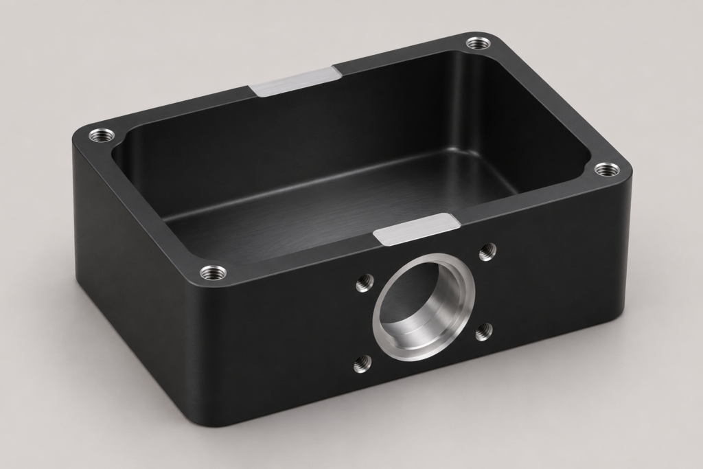
Illustrative project: finish and masking concept
A housing: from machined features to the final fit
Illustrative project — instrument housing
Consider an aluminium housing with a locating bore, a mounting face and a black anodised exterior. The purchase specification needs to describe both the appearance and the surfaces that locate the internal assembly.
A useful manufacturing plan separates rough and finish machining, identifies the bore and electrical contact areas requiring masking, and defines the dimensions to verify after treatment. The drawing must state whether the fit applies before or after finishing. If a later batch changes the coating or mating component, that interface needs review again.
This illustration shows how machining, masking and final measurement connect. It is a design scenario rather than a customer delivery or measured inspection result.
Materials for custom CNC parts
Start with the part’s environment, loading and mating components, then specify the grade and condition. Family names alone do not define a purchase specification. The examples below are supply options for review, rather than a stock list or permission to substitute one grade for another.
Metals
Engineering plastics
Surface finishes without losing the fit
Choose the surface treatment alongside the material and functional dimensions. Specialist finishing is coordinated through selected partners; the required process and final acceptance state form part of the quotation.
State whether critical dimensions apply before or after finishing. Coating thickness is not a universal conversion for dimensional change. Agree the treatment, geometry, masking and final measurement requirements together.
CNC capability and tolerance guidance
These figures help screen a drawing for review. They describe different processes and selected features: the largest part envelope, smallest feature and tightest tolerance cannot be combined into one blanket capability. Drawing requirements and the agreed manufacturing and inspection route control acceptance. Unspecified dimensions and any general-tolerance standard are agreed before production.
If the drawing calls for a closer fit, specialised grinding or an unusual geometric tolerance, highlight that feature for a separate feasibility and measurement review. A size tolerance alone does not specify flatness, position, roundness or runout.
Design details worth discussing before machining
A practical review targets the features that add machining or verification work, while preserving the part’s function.
Deep pockets and internal corners: Cutter reach, corner radius and chip removal can limit access. Identify the envelope the mating part actually needs before requiring a sharp internal corner.
Thin walls and slender sections: Cutting forces and clamping can move the feature. More support, a different sequence or a customer-approved geometry change may be needed.
Holes and threads: State diameter, effective depth, thread specification and the required fit. Blind-hole bottoms and long small-diameter holes need a feasible tool and inspection route.
Features on several faces: Clear datums help relate hole positions and interfaces across setups. Tight relationships between faces may change the fixture or process choice.
Tolerances and cosmetic areas: Apply close tolerances to the dimensions that control function, and identify visible faces separately. Extra finishing passes, masking and inspection add work when applied across the whole part.
Any recommended design revision remains subject to your approval before production.
Components for equipment and instrument teams
Industrial automation and special equipment
Camera and sensor mounts, end-effector brackets and locating plates provide the mounting and positioning interfaces within equipment assemblies. Guide blocks, shafts and sleeves add sliding or rotational interfaces. We make these metal and plastic components to the specified material, mounting dimensions and load-related requirements, retaining the approved revision for repeat orders.
Measurement, testing and laboratory instruments
Instrument housings support internal components; sample locating parts and test fixtures establish the interfaces used during positioning or testing. Machining and finishing are planned around the specified locating surfaces, finish-sensitive fits and grounding areas as well as the exterior. Cleanliness, chemical environment, special cleaning, testing and application-specific qualification need agreement for the project.
CNC machining FAQ
Get an engineering quotation for your CNC parts
Send your available drawing or model, quantities and intended use. If the material or process is undecided, describe the operating conditions and mating features—you can start the enquiry with what you know.
We will review the project and return the proposed manufacturing route, price for the stated quantities, finishing and inspection scope, and manufacturing lead time. Include your target date and receiving country so dispatch and delivery can be considered separately.